Panasonic se ch 10 service manual

This is the 16 pages manual for panasonic se ch 10 service manual.
Read or download the pdf for free. If you want to contribute, please upload pdfs to audioservicemanuals.wetransfer.com.

Page: 1 / 16
panasonic se ch 10 service manual

Extracted text from panasonic se ch 10 service manual (Ocr-read)


Page 1

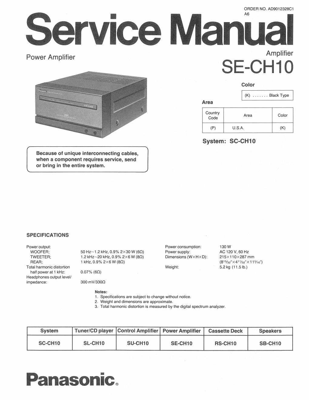
ORDER NO. AD901232801

Service Manual

. . Am llfier
Power Amplifier p
Color
(K) ....... Black Type
Area
Country
Code Area Color
(P) U.S.A. (K)
System: SC-CH10
Because of unique interconnecting cables,
when a component requires service, send
or bring in the entire system.
SPECIFICATIONS
Power output: Power consumption: 130 W
WOOFEFl; 50 Hz~1.2 kHz, 0.9% 2X30 W (60) Power supply: AC 120 V, 60 Hz
TWEETEFl; 1.2 KHZNZO kHz, 0.9% 2X6W(BQ) Dimensions (WXHXD): 215x110><287 mrn
REAR; 1 kHz, 0.9% 2X6 W (80) (85/32><4 1/32">< 1 1 5/15")
Total harmonic distortion Weight: 5.2 kg (11.5 lb.)
half power at 1 kHz: 0.07% (60)
Headphones output levell
impedance: 300 mV/33OO
Notes:
1. Specifications are subject to change without notice.
2. Weight and dimensions are approximate.
3. Total harmonic distortion is measured by the digital spectrum analyzer.
System Tuner/CD player Control Amplifier Power Amplifier Cassette Deck Speakers
SC-CH10 SL-CH10 SU-CH10 SE-CH10 RS-CH1O SB-CH1O

Panasonic.

Page 2

SE-CH10

CONTENTS

Page Page
SAFETY PRECAUTION ................................. 2 SCHEMATIC DIAGRAM .............................. 8~10
BEFORE REPAIR ......... 2 PRINTED CIRCUIT BOARDS AND
PROTECTION CIRCUITRY ... ..3 WIRING CONNECTION DIAGRAM .................. 11,12
LOCATION OF CONTROLS . . .3 BLOCK DIAGRAM ................................. 13, 14
OPERATION ................. . .4 REPLACEMENT PARTS LIST . . .15N18
DISASSEMBLY INSTRUCTIONS .......................... 5 CABINET PARTS LOCATION ........................ 19, 20
NOTES:

Refer to the service manual for Model No. SU-CH10, Order No. AD901233001 for
information on ACCESSORIES, INSTALLATION OF THE SYSTEM, CONNECTIONS and
PACKAGING.

SAFETY PRECAUTION

Before servicing, unplug the power cord to prevent an electric shock.

When replacing parts, use only manufacturers recommended components for safety.

Check the condition of the power cord. Replace if wear or damage is evident.

After servicing, be sure to restore the lead dress, insulation carries, insulation papers, shields, etc.

Before returning the serviced equipment to the customer, be sure to make the following insulation resistance test to prevent the
customer from being exposed to a shock hazard.

OINSULATION RESISTANCE TEST

1. Unplug the power cord and short the two prongs oi the plug with a jumper wire.

2. Turn on the power switch.

3. Measure the resistance value with ohmmeter between the jumpered AC plug and each exposed metal cabinet part, such as
screwheads antenna, control shafts, handle brackets, etc. Equipment with antenna terminals should read between 3 MO and
52 M0 to all exposed parts. (Fig. A) Equipment without antenna terminals should read approximately infinity to all exposed
parts. (Fig. B)

SIMPSON.

Note: Some exposed parts may be isolated from the chassis by design. These will read infinity.

Antenna
terminal

Exposed Exposed
metal metal
part part
Ohmmeter Ohmmeter
(Flg- A) (Fig, B)
Resistance-*3 M0752 MO ReSIstance-Approx. co

4. lithe measurement is outside the specified limits, there is a possibility of a shock hazard. The equipment should be repaired and
rechecked before it is returned to the customer.

BEFORE REPAIR

(1) Turn off the power supply. Using a 109, 10 W resistor, connect both ends of power supply capacitors (C703, 0704) in order to discharge
the voltage.

(2) Before turning the power supply on, after completion of repair, slowly apply the primary voltage by using a power supply voltage controller
to make sure that the consumed current at 120 V, 60 Hz in NO SIGNAL mode is 275~825 mA.