Panasonic sa pm15 service manual

This is the 30 pages manual for panasonic sa pm15 service manual.
Read or download the pdf for free. If you want to contribute, please upload pdfs to audioservicemanuals.wetransfer.com.

Page: 1 / 30
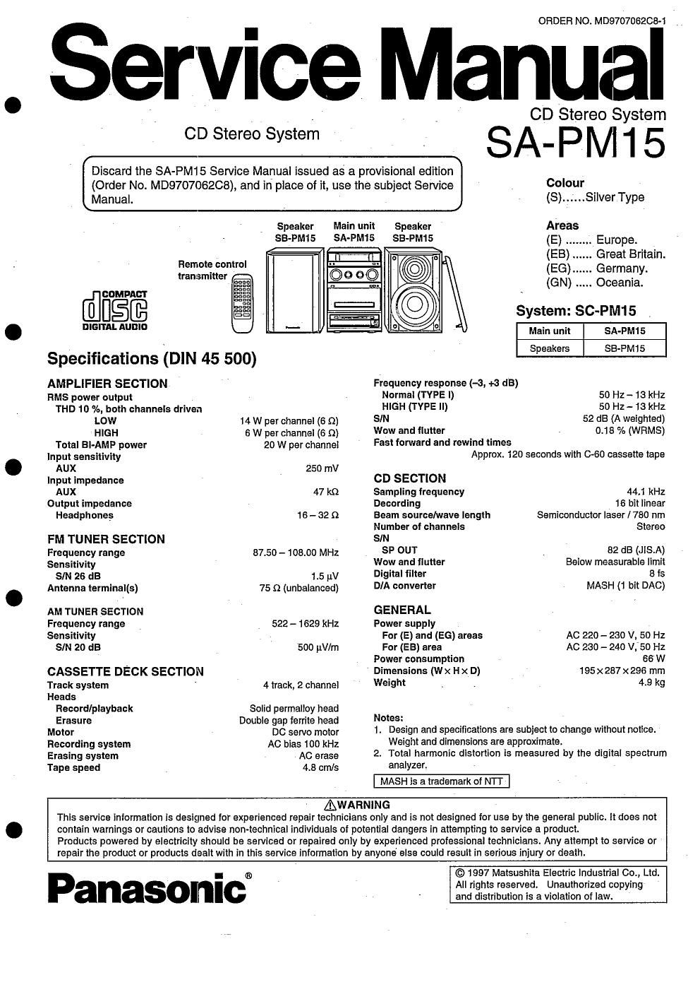
panasonic sa pm15 service manual

Extracted text from panasonic sa pm15 service manual (Ocr-read)


Page 1

ORDER NO. MD970706208- 1

Service Manual

CD Stereo System

Discard the SA-PM15 Service Manual issued as a provisional edition

CD Stereo System

SA-PIVI15

(Order No. MD9707062C8), and in place of it, use the subject Service COIOUI
Manual. (S)..;...SIiver Type
Speaker Main unit Speaker Areas
SB-PM15 SA-PM15 SB-PM15 (E) Europe.
(EB) .. .. Great Britain.
Hem °°mr°l (EG) .. .. Germany.
transmitter .
.5 (GN) ..... Oceania.
CDMPAE'I' =2
La
USE 'm System: SC-PM15
3"- MB' Main unit SA-PM15
Speakers SB-PM15
Specifications (DIN 45 500)
AMPLIFIER SECTION Frequency response (-3, +3 dB)
HMS power output Normal (TYPE I) 50 Hz- 13 kHz
THD 10 %, both channels driven HIGH (TVPE ll) 50 ['12- )3 kHZ
Low 14 w per channel (a c) SIN 52 dB (A weighted)
HIGH 5 w per channel (5 9) Wow and flutter 0.18 % (WRMS)
Total Bl-AMP power 20 W per channel Fast "1"an and rewind times
input sensitivity Approx. 120 seconds with 0-60 cassette tape
AUX 250 mV
input impedance CD SECTION
AUX 47 kn Sampling frequency 44,1 kHz
Output impedance Decanting 18 bit linear
Headphones 16 - 32 (2 Beam source/wave length Semiconductor laser (780 nm
Number cl channels Stereo
FM TUNER SECTION SIN
Frequency range 87.50 - 108.00 MHz SP OUT 52 13 (JlS.A)
Sensitivity Wow and flutter Below measurable limit
SIN 25 dB 15 11V Digital filter 8 f5
Antenna terminai(s) 75 n (unbalanced) D/A converter MASH (1 bit DAG)
AM TUNER SECTION GENERAL
Frequency range 522 - 1629 kHz Power supply
Sensitivity For (E) and (EG) areas AC 220- 230 V, 50 Hz
SIN 20 dB 500 pV/m For (EB) area AC 2130 - 240 V. 50 Hz
Power consumption 66W
CASSETTE DECK SECTION Dimensions (Wx Hx D) 195x287x296 mm
Track system 4 track, 2 channel Web 43 kg
Heads
Record/playback Solid permelloy head
Erasure Double gap ferrite head "0'95:
Motor DC servo motor 1. Design and specifications are subject to change without notice.

Recording system

AC bias 100 kHz

Weight and dimensions are approximate.

Erasing system AC erase 2. Total hamionic distortion is measured by the digital spectrum
Tape speed 4.8 cm/s analyzer.
MASH is a trademark of NIT
AWARNING

This service information is designed tor experienced repair technicians only and is not designed for use by the general public. it does not
contain warnings or cautions to advise non-technical individuals of potential dangers in attempting to service a product.
Products powered by electricity should be serviced or repaired only by experienced professional technicians. Any attempt to service or

repair the product or products dealt with in this service information by anyone else could result in serious injury or death.

Panasornicl

© 1997 Matsushita Electric Industrial 00., Ltd.
All rights reserved. Unauthorized copying
and distribution is a violation of law.

Page 2

SL-PM15 I

I Schematic Diagram

Pager
CD SEFtVO CIRCUIT ......................................... 19. 20
E MECHANISM CONTROL CIRCUIT.. 21, 22

MECHANISM CIRCUIT.
I! FerUNER CIRCUIT
MOTOR (SLIDE PANEL) CIRCUIT ..


|]| OPERATION (3) CIRCUIT
VOLUME CIRCUIT


OPERATION (4) CIRCUIT
OPERATION (5) CIRcurr
OPERATION (c) CIRCUIT ..................................... 26
LOADING MOTOR CIRCUIT ................................ 27
E MAIN CIRCUIT ................................................... 27- so
[3 POWER SUPPLY CIRCUIT .................................. 30

0 Indicated voltage values are the standard values for the unit
measured by the DC electronic circuit tester (high-impedance) with
the chassis taken as standard. Therefore, there may exist some
errors in the voltage values, depending on the internal Impedance Of
the DC circuit tester.

his mark CD STOP

( ).. .. co PLAYBACK (1kHz, L+R, OdB)
< .. FM

{- . .. AM

{( .. DECK PLAYBACK

.. DECK RECORDING

I- important saiety notice:
Components identified by A; mark have special characteristics
important for safety.
Furthermore. special parts which have purposes of fire-retardant
(resistors), high-quality sound (capacitors), low-noise (resistors),
etc. are used. When replacing any of components, be sure to use
only manufacturers specified parts show in the parts list.

- Caution!
IO and LS] are sensitive to static electricity.
Secondary trouble can be prevented by taking care during repair.
Cover the parts boxes made of plastics with aluminum toil.
Ground the soldering iron.
Put a conductive mat on the work table.
DO not touch the legs of IC or LSI with the fingers directly.

- Signal Line

CD Signal Line

FM Signal Line

FM OSC Signal Line

I LAMP CIRCUIT ..........................................
OPERATION (1) CIRCUIT ........... . ......................... 25
OPERATION (2) CIRCUIT ..................................... 26
o This schematic diagram may be modified at any time with the development of new technology.
- S701 : CD rest switch.

I S790 : CD tray Open detect switch,

- S791 : CD tray close detect switch.

I 5801 :Tuner/band select switch. (T UNEFi/BAND)

- 8802 :Tuning mode select switch. (TUNE MODE)

C 8803 : Memory/set switch. (MEMORY/SET)

- 8804 : Record/record pause switch. (OIOII REC/REC
PAUSE)

- secs : Rewind TPS switch. (REW/-)

- saos : Fast forward switch. (FF/-)

- 8307 : AUX switch. (AUX)

| $808 : Cassette stop switch. (I)

- $809 : Cassette play/direction switch. (4 D)

t 3310 : Cassette holder open switch. (A)

- 8311 :Tuningltime adjust switch. (l U NE/TIME ADJ DOWN/-)
I 3812 :Tuning/tlme adjust switch. (TUNE/TIME ADJ UPI +)

- $813 : Glide panel open/close switch. (OPEN/CLOSE)

. $614 : Clock/timer switch. (CLOCK/TIMER)

I 8815 : Play timer/record timer switch. (SPLAY/ 6 REC)

I 8816 : Power switch. (POWER)

~ 8317 : CD edit switch. (CD EDIT)

s 5618 : Skip/search switch. (K4 SKIP)

- 5819 : Skip/search switch. (PH SKIP)

0 $820 : CD stop switch. (I STOP)

- $821 : CD play/pause switch. (>l ll PLAY/PAUSE)

C 8822 : CD tray Open/close switch. (AICLOSE)

- 5971 : Deck mode detect switch.

a $972 : Deck half detect switch.

t 3973 : Deck Croz tape detect switch.

0 5974 : Deck reverse side record prevention tab detect switch.
- 5975 : Deck {onward side record prevention tab detect switCh.
a Vfiam : Volume control encoder. (VOLUME)

I VRBOZ : Bass control VR, (BASS)

- VRaoa :Trebte control VFt, (T HEBLE)

AM 080 Signal Line
AM 030 SIGNAL Line

Tape Playback Signal Line

Tape Recording Signal Line

_13_