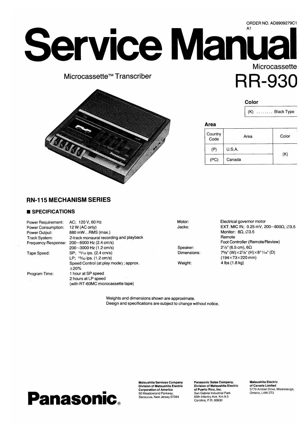
Panasonic rr 930 service manual
This is the 15 pages manual for panasonic rr 930 service manual.
Read or download the pdf for free. If you want to contribute, please upload pdfs to audioservicemanuals.wetransfer.com.
Extracted text from panasonic rr 930 service manual (Ocr-read)
Page 1
ORDER NO. A0890927QC1
Service Manual
Microcassette
MicrocassetteTM Transcriber R R _ 9 3 0
Color
(K) ....... Black Type
Area
Country
Code Area Color
(F) U .S.A:
(K)
(PC) Canada
RN-115 MECHANISM SERIES
I SPECIFICATIONS
Power Requirement: AC; 120 V, 60 Hz Motor: Electrical governor motor
Power Consumption: 12 W (AC only) Jacks: EXT. MIC IN; 025 mV, 200~600Q (233.5
Power Output: 880 mW.. .RMS (max) Monitor: 80. (53.5
Track System: 2-track monaural recording and playback Remote
Frequency Response: 200~6000 Hz (2.4 cm/s) Foot Controller (Remote/Review)
200~3000 Hz (1 .2 cm/s) Speaker: 2V2 (65 cm), 60
Tape Speed: SP; 15/1sips (2.4 chs) Dimensions: 7% (W)><27/s (H)><8 1/16" (D)
LP; 15/:2ipst (1.2 cm/s) (194x73x220 mm)
Speed Control (at play mode) ; approx. Weight: 4 lbs (1 .8 kg)
i 20 %
Program Time: 1 hour at SP speed
2 hours at LP speed
(with RT-GOMC microcassette tape)
Weights and dimensions shown are approximate.
Design and specifications are subject to change without notice:
Mamuthlta Services Compnny Panasonic Sales Company. Mutsushita Electric
Division ui Malsushila Electric Dlvlsion cl Malsusiilll Electric or Canada Limited
Corporation oi America of Pueno Rico, Inc. 5770 Ambler Drive, Mississauga,
so Meadowiand Parkway, San Gabriel industrial Perk Ontario, L4W 2T3
I
Secaucus, New Jersey 07094 55m Inlanlry Ave. Km.9.5
® Carolina, PR. 00630
Page 2
SAFETY PRECAUTIONS
Before servicing. unplug the power cord to prevent an electric shock.
When replacing parts. use only manufacturers recommended components for saiety,
Check the condition of the power cord. Replace ii wear or damage is evident.
After servicing, be sure to restore the lead dress, insulation barriers, insulation sheets, shields, etc.
Before returning the serviced equipment to the customer, be sure to make the iollowing
insulation resistance test lo prevent the customer from being exposed to a shock hazard.
IMPN.
INSULATION TEST
1. Unplug the power cord and short the two prongs of the plug with a jumper wire.
2. Turn on the power switch.
3. Measure the resistance value with the ohmmeter between the jumpered AC plug and each exposed
metal cabinet part, such as screwheads. antenna, control shafts, handle brackets, etc. Equipment
with antenna terminals should read between SM) and 5.2 MD to all exposed parts. (Fig. 1)
Equipment without antenna terminals should read approximately infinity to all exposed parts.
(Fig- 2)
sNote: Some exposed parts may be isolated Irom the chassis by design. These will read
infinity.
4. If the measurement is outside the specified limits, there is a possibility of a shock hazard.
The equipment should be repaired and rechecked beicre it is returned to the customer.
LOCATION OF CONTROLS AND COMPONENTS
Antenna
lermrnal NJ I
EXDosed 9
melal
pail
Exposed
MCIOI
pail
0 Speaker (60, 6.5 cm)
9 Power Switch (POWER)
9 Power Indicator (POWER)
0 Recording indicator (REC)
a Quick Erase Indicator
(QUICK ERASE)
9 Tape Running Indicator
(TAPE RUN)
0 Tape Counter and Reset Button
(COUNTER)
9 Cassette Holder
9 Stop/Elect Button
(I STOP/A EJECT)
(a Fast Forward/Cue Button
(<4 FF/CUE)
0 Playback Button (4 PLAY)
® Rewind/Review Button
(REW/REV >>)
m Record Button( 0-)
0 Pause Button (I I PAUSE)
6 Volume Control (VOLUME)
0 Built-In Microphone (MIC)
0 Tone Control (TONE)
0 Auto Back Space Control
(BACK SPACE CONTROL)
0 Tape Speed Control
(SPEED CONTROL)
® Tape Speed Selector
(TAPE SPEED)
@ Monitor Jack (MONITOR)
(an, (53.5)
Q External Microphone Jack (MIC)
(6000, $3.5)
w Remote Jack (REMOTE)
® Foot Controller Jack
(REMOTE/REVIEW)
@ AC Power cord
Ohmmeler
F ig, 1
Resistance : 3 M9 -5 2 M9
Oflmmeler
Fig. 2
Resistance = Approx no
OACCESSORIES
/-"fl
Head Set
Foot Controller
® Back Space Pedal
(BACK SPACE)
® Start Pedal (START)
\_______/