Panasonic rq a 220 gu service manual

This is the 23 pages manual for panasonic rq a 220 gu service manual.
Read or download the pdf for free. If you want to contribute, please upload pdfs to audioservicemanuals.wetransfer.com.

Page: 1 / 23
panasonic rq a 220 gu service manual

Extracted text from panasonic rq a 220 gu service manual (Ocr-read)


Page 1

TD03040790C3

Service Manual

Specification

Radio:

Frequency Range: FM; 87.5 ~ 108.0MHz

AM; 520 ~1610kHz

intermediate Frequency: FM; 10.7MHz

AM 455 kHz

FM; 5 011 MV/OJ rnW output
(-3dB Limit, Sens)

AM; 562 MV/mIOJ mW output
(MAX,Sen5)

Cassette Player/Recorder:

Track system: 4 track,2 channel,Stereo

Sensitivity:

Recorder system: AC bias
Erasing system: Magnet erase
Monitor system: Variable

Frequency range: Playback: 40 ~ 16000 Hz (-6 dB)

Recording; 70 ~ 8000 Hz

Tape Speed: 4.8cmls 1.6cm/s
Wow & Flutter: 0,12% (WRMS)
General
lnputjack: STEREO MIC
06 mV (200 ~ 6009)
Output jack: Headphones;50§23 $233.5
Power Output:
Speaker: 490mW+490rnW+20mW (RMS.. .max)
Earphones: 3mW+3mW (RMS...max)
Speaker: 4.5 cm x 2
1.1 cm x 1

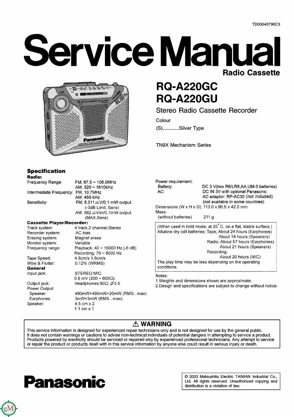
Radio Cassette

RQ-A220GC
RQ-A220GU

Stereo Radio Cassette Recorder

Colour
(8) ............ Silver Type

TN9X Mechanism Series

Power requirement:
Battery: DC 3 V(two R6/LR6,AA,UM-3 batteries)
AC: DC N (W with optional Panasonic
AC adaptor: RP-Acso (not included)
(not available in some countries)
Dimensions (W x H x D): 113.0 x 86.6 x 42.0 mm
Mass:

(without batteries) 211 g

(When used in hold mode, at 25° C, on a flat, stable surface.)
Alkaline dry cdll batteries; Tape; About 24 hours (Earphones)
About 14 hours (Speakers)
Radio; About 57 hours (Earphones)
About 21 hours (Speakers)
Recording:
About 20 hours (MC)
The play time may be less depending on the operating
conditions.

Notes:
1.Weights and dimensions shown are approximate.
2.Design and specifications are subject to change without notice.

AWARNING

This service information is designed for experienced repair technicians only and is not designed for use by the general public.

It does not contain warnings or cautions to advise non-technical individuals of potential dangers in attempting to service a product.
Products powered by electricity should be serviced or repaired only by experienced prolessional technicians Any attempt to service
or repair the product or products dealt with in this service iniormation by anyone else could result in serious injury or death

Panasonic

© 2003 Matsushila Electric TAIWAN Industrial 00.,
Ltd. All rights reserved. Unauthorized copying and
distribution is a violation of law.

Page 2

RG-AHOGC l RO-AMGU

CONTENTS

Page

1 Location of Controls --------------------------------------------------------------- 2
2 Operation Checks and Component Replacement Prooedureas
2.1. How to Removal of the Cassette Lid ------------------------------- 3

2.2. Removal of the Battery cover and Rear Cabinet -------------- 3

2.3. Removal of the Main P.C.B. ------------------------------------------- 4

2.4. Removal of the Tuner Cover,Tuner knob and Dial Pointer4

2.5. Remove of the ANT Chassis ------------------------------------------ 5

2.6. Removal 01 the MIC Ornament --------------------------------------- 5

2.7. Removal of the REC Safety Lever ................
2.8. How to Replace the Tuner Knob and Dial Point
2.9. Removal of the Mechanism and Middle Cabinet .............. 6
2.10. Removal of the PL Bracket ............................................. 6
2.11. Removal of the RIP Head and Erase Head
2.12. Removal of the Motor Ass'y and Belt ---------
2-13. Removal of the Pinch Rooler Assy --------------------------------- 7
2-14. Removal of the Speaker and Buzzer ------------------------------- 8

1 Location of Controls

Hand Strap Link
PAUSE Button
b PLAY Button

0 GE Button

TAPE/FM/AM

OFF
Built-in MIC

TUNING-

STEREO MIC Jack
(PLUG IN POWER)

VOLUME

O Headphones


Lights when a \ l ,
station is - -
tuned in / | \

SPEAKERS

http : / /get:MANUAL . com

Page

2.15. Removal of the REC Mode Knob .................................... 3
2.16. How to Replace the Cassette Lid and Torque Spring '8
2-17. Notice for assembling the Circuit Board .................. .9

3 Block Diagram ---------------------------------------------------------------------- 10
4 Type Illustration of lOs, Tran stars and Diodes
5 Schematic Diagram

5.1. Schematic Diagram Notes
5.2. Schematic Diagram ------------------------------------------------------ 11
6 Printed Circuit Board Diagramm-
7 Measurements and Adjustments

8 Mechanism Parts Location --------------------------------------------------- 17

9 Cablnet Parts Location --------------------------------------------------------- 19
10 Packaging

...... ........2°

11 Replacement Parts List --------------------------------------------------------- 20

FM MODE/BF.
STEREO/MONO

- Db FF/CUE

-<< REW/ REV

REC MODE (NORM II 3X)

l STOP Button

BATTERY COVER (Back)

DC IN sue-Ge)