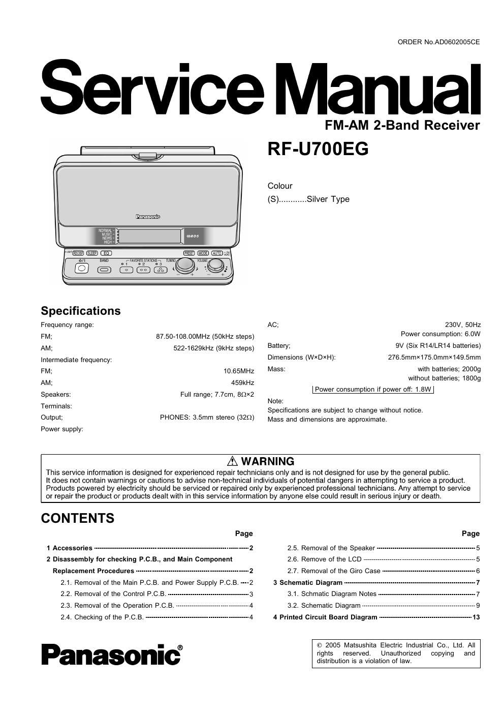
Panasonic rf u 700 eg service manual
This is the 26 pages manual for panasonic rf u 700 eg service manual.
Read or download the pdf for free. If you want to contribute, please upload pdfs to audioservicemanuals.wetransfer.com.
Extracted text from panasonic rf u 700 eg service manual (Ocr-read)
Page 1
ORDER N0.AD0602005CE
Service Manual
Spedficafions
Frequency range:
FM; 87.50-108.00MHZ (50kHz steps)
AM; 522-1629kHZ (9kHz steps)
Intermediate frequency:
FM; 10.65MHZ
AM; 459kHz
Speakers: Full range; 7.7cm, 89X2
Terminals:
Output; PHONES: 3.5mm stereo (329)
Power supply:
FM-AM 2-Band Receiver
RF-U700EG
Colour
(8). .Silver Type
AC; 230V, 50Hz
Power consumption: 6.0W
Battery; 9V (Six R14/LR14 batteries)
Dimensions (WXDXH): 276.5mmX175.0mmX149.5mm
Mass: with batteries; 2000g
without batteries; 1800g
Power consumption if power off: 1.8W
Note:
Specifications are subject to change without notice.
Mass and dimensions are approximate.
AWARNING
This service information is designed for experienced repair technicians only and is not designed for use by the general public.
It does not contain warnings or cautions to advise non-technical individuals of potential dangers in attempting to service a product.
Products powered by electricity should be serviced or repaired only by experienced professional technicians. Any attempt to service
or repair the product or products dealt with in this service information by anyone else could result in serious injury or death.
CONTENTS
Page
1 Accessories ---------------------------------------------------------------------------- 2
2 Disassembly for checking P.C.B., and Main Component
Replacement Procedures -- -------------------------------------------- 2
2.1. Removal of the Main PCB. and Power Supply P.C.B. ----2
2.2. Removal of the Control P.C.B. ---------------------------------------- 3
2.3. Removal of the Operation P.C.B. ------------------------------------ 4
2.4. Checking of the P.C.B. --------------------------------------------------- 4
Panasonic
Page
2.5. Removal of the Speaker ................................................. 5
2.6. Remove of the LCD ------------------------------------------------------- 5
2.7. Removal of the Giro Case ---------------------------------------------- 5
3 Schematic Diagram ----------------------------------------------------------------- 7
3.1. Schmatic Diagram Notes ................................................ 7
3.2. Schematic Diagram -------------------------------------------------------- g
4 Printed Circuit Board Diagram ---------------------------------------------- 13
© 2005 Matsushita Electric Industrial Co., Ltd. All
rights reserved. Unauthorized copying and
distribution is a violation of law.
Page 2
5 Type Illustration of IC's, Transistors and Diodes ................. 15
6 Wiring Connection Diagram
7 Terminal Function of lc's
7.1. ICSO2 (CZCBYYOOOO74) :System Control / LCD Drive---17
8 Self Diagnosis and Lcd Test -------------
8.1. Setting of self diagnostic Function
8.2. Existing the Service Mode -------------------------------------------- 18
8.3. Error Codes -----
9 Check and Adjustment-
1 Accessories
- Power supply code(RJA0019-D) ................................... 1pc,
9.1. Tools and Instruments Required ................................... 1g
9.2. Preparations--- ".19
9.3. FM Adjustment ...1g
9.4. AM Adjustment ------------------------------------------------------------ 1g
9.5. Adjustment Point-- -20
10 Replacement Parts List-- -20
11 Cabinet Parts Location --------------------------------------------------------- 25
12 Packaging ----------------------------------------------------------------------------- 26
2 Disassembly for checking P.C.B., and Main Component
Replacement Procedures
ATTENTION SERVICER"
Some chassis components may have sharp edges.
Be careful when disassembling and sen/icing.
1.This section describes procedures for checking the operation of the major printed circuit boards and replacing the
main components.
2. For assembly after operation checks or replacement, reverse the respective procedures.
Special reassembly procedures are described only when required.
3.Select items from the following index when checks or replacement are required.
- Removal of the Main P.C.B. and Power Supply P.C.B.
- Removal of the Control P.C.B.
- Removal of the Operation P.C.B.
- Checking of the PCB.
- Removal of the Speaker
- Removal of the LCD
- Removal of the Giro Case
2.1. Removal of the Main P.C.B.
and Power Supply P.C.B.
(Step 1) 9 e
(Step 4)
Remove the front cabinet ass'y.
Front cabinet ass'y
(Step 2)
Pull out the socket
from connector
(CP301).
Pull out the FFC from
connector (CS101).