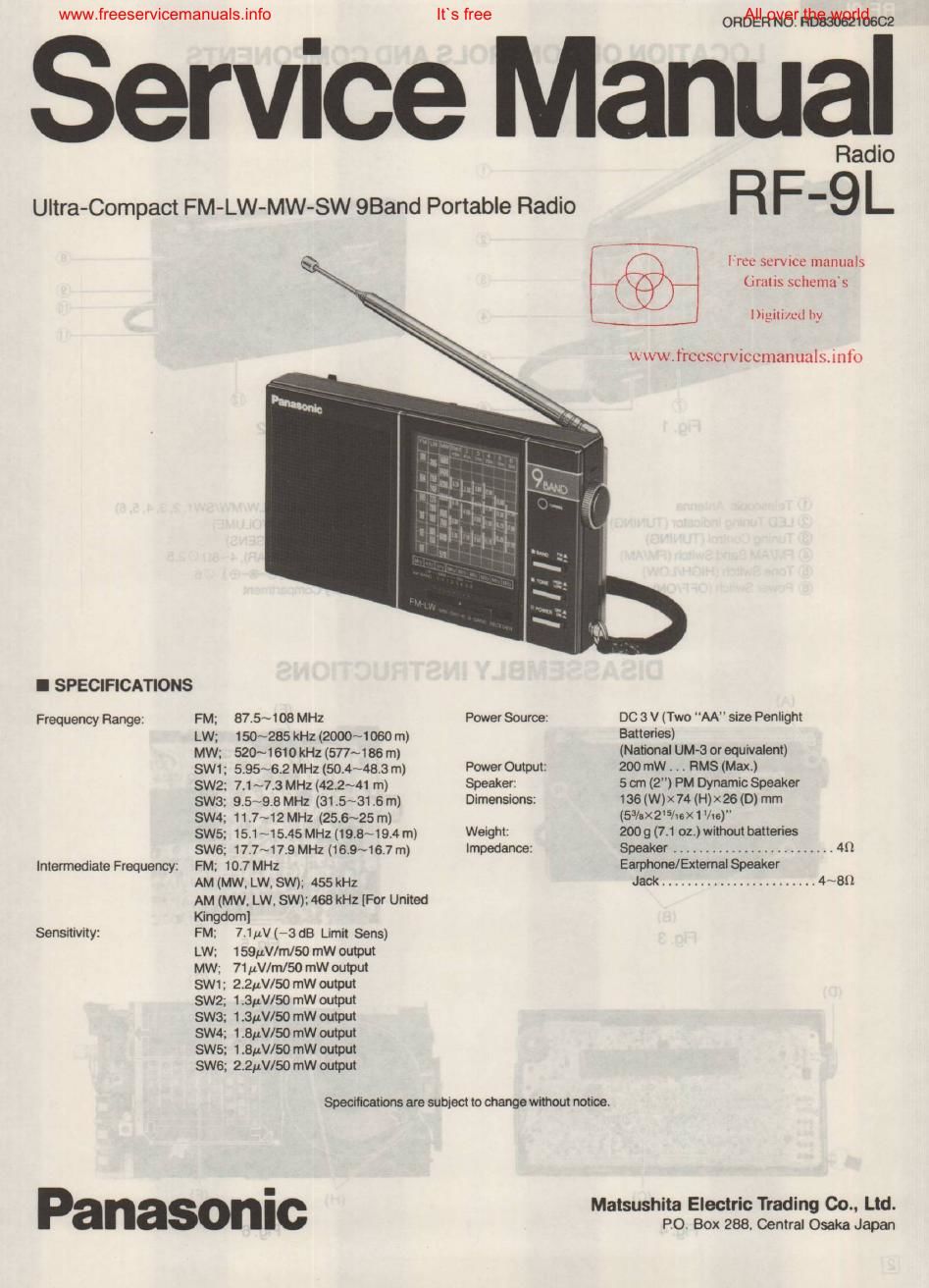
Panasonic rf 9l service manual
This is the 8 pages manual for panasonic rf 9l service manual.
Read or download the pdf for free. If you want to contribute, please upload pdfs to audioservicemanuals.wetransfer.com.
Extracted text from panasonic rf 9l service manual (Ocr-read)
Page 2
-ervicemanuals.info
LOCATION OF CONTROLS AND COMPONENTS
@ Telescopic Antenna
® LED Tuning Indicator (TUNING)
© Tuning Control (TUNING)
@ FM/AM Band Switch (FM/AM)
© Tone Switch (HIGH/LOW)
Power Switch (OFF/ON)
Fig. 2
(3 AM Send Switch (LW/MW/SW1,2.3. 4, 5,6)
Volume Control (VOLUME)
DX-Local Switch (SENS)
EarphoneJack (EAR), 4~an (25 2.5
@ DClnputJack(e-©-®) as
® Battery Compartment
DISASSEMBLY INSTRUCTIONS
(E)
When removing the knob, (M) Band Switch Lever
spring and steel ball will go out
Fig. 7
Its free
All over the world
MEASUREMENTS AND ADJUSTMENT
Cathode / Anode
1
Fig.8 H 1 Fig. 10
Procedure To remove-. Remove-. Shown in Hg.-.
1 Telescopic Antenna Screw (2x 20) ......................... (A) x1 3
2 , Remove the battery cover. -
Rear Cabinet .
3 Screw (2x20) .................... (B) x2 3
4 . . Screw(2x20) ............. ...(C)>
5 Cl Knob ............................ (D) x 1 4
6 Unsolder LED .................... (E)x2 5
7 Push the catch in the direction of arrow (F) and 6
remove the dial scale (G) ......... (F)x4. (G) x1
8 Push the catch in the direction of arrow and 6
remove the speaker ............... (H) x 2
9 Dial Chassis ~1. 2 Screw (2x4) ....................... (I)xt 7
10 Screw(1.7x2) ......................... (J)X1 7
11 Remove the dial drum in the direction of arrow and 8
fix it to the dial chassis.
12 Push the catch in the direction of arrow and 9
remove dial chassis. .................... (K)X2
13 Push the catch in the direction at arrow and 7
remove the stopper ...................... (L) x 1
d k b
14 Ban no Push the catch in the direcfion of arrow and 7
remove the lump. ...................... (M) x 5
t1 . Insert the switch into the hole of band switch lever. refer to fig. 7.
t2. Resolder LED. refer to fig. 10.
DIAL THREADING
l65.5mrn
+5
4 Turns
I ALIGNMENT INSTRUCflON
READ CAREFULLY BEFORE ATTEMPTING ALIGNMENT
1 . Set volume control to maximum. 5. Set DX- local switch to OX.
2. Set tone switch to high. 6. Set power source voltage to 3 V DC.
3. Set band SWIICh t0 LWv MW. SW1 TS or FM- 7. Output of signal generator should be no higher than
4. Set power switch to ON. necessary to obtain an output reading.
I MW, LW and SW1 ~5 ALIGNMENT
SIGNAL GENERATOR or INDICATOR
BAND SWEEP GENERATOR 339132?" (E&58w$? ADJUSTMENT REMARKS
CONNECTIONS j FREQUENCY or SCOPE)
AM-IF ALIGNMENT
Fashion loop of 455 kHz j
several turns of 468 kHz Point of non- Output meter T2 (AM 1st) Adjust for maximum
(1) MW wire and radiate For UK.) l interference. (on/ across voice coil. T3 (AM 2nd) output.
signal into loop of °/o MOd. about 600 kHz)
receiver. at 400 kHz j
LW -RF ALIGNMENT
Output meter L1 3 (LW OSC Adjust tor maximum
(2) LW 145 kHz 145 kHz across voice Coil) output. Adjust L1 by
(Raterto Fig. 15) coil (:1) L1 (LW ANT movi coil bobbin
L i Coil) along en'ite core.
kH CT4 (LTW OSC Adjust tor maximum
U 285 z ,, rimmer) output.
3) Lw 285 kHz (Refer to Hg. 15) CT1 (LW ANT Repeat steps (2)
Trimmer) and (3).
MW-RF ALIGNMENT
550 kHz Output meter L14(MW OSC Adjust for maximum
(4) MW 550 kHz (Reler to across voice Coil output. Adjust L2 by
Fig.15) coil (1)L2(MW mot/in DOII bobbin
ANT Coil) along errite core.
1,500 kHz CT6 (MW 030 Adjust for maximum
(5) MW l' 1 .500 kHz (Reterto ,. Trimmer) output.
Fig. 15) 0T5 (MW ANT Repeat steps (4)
Trimmer) and (5).
(«1) Cement antenna bobbin with wax alter completing alignment.
_ SW1 -BE ALIG ENT
Connect $395;th 6.06 MHz Output meter L1 5 (SW1 osc Adjust tor maximum
(6) SW1 I 39 F 5,06 MHz (Refer to across voice Coil) output.
39" (3 0 p " Figt15) coil La (SW1 ANT
Negative side to Coil)
test point V.
SW2-RF ALIG \IMENT
7.2 MHz Output meter Li 6 (SW2 080
(7) SW2 ' 72 MHz (Refer to across voice Coil) Adjust for maximum
Fig. 15) coil L4 (sw2 ANT output.
Coil)
SWS-RF ALIGNMENT
9.631 MHz Output meter L17 (SW3 080
(8) SW3 9.631 MHz (Refer to across voice Coil Adjust for maximum
Fig. 15) coil L5 (SW3 AN output.
Coil)
SW4-RF ALIGNMENT
1 1 .842 MHz Output meter L18 (SW4 080
(9) SW4 " 1 1 .842 MHz (Refer to acres voice Coil Adjust tor maximum
Fig. 15) coil L6 (SW4 ANT output.
Coil)
SWS-RF ALIGNMENT
15.25 MHz Output meter L19 (SW5 030
(10) SW5 ,. 15.25 MHz (Refer to across voice Col!) Adjust lor maximum
Fig. 15) coil L7(SW5 AN output.
Coil)
SWS-HF ALIGNMENT
17.633 MHz Output meter L20 (SW6 080
(11 ) SW6 1 7.838 MHx (Refer to across voice Coil) Adjust for maximum
Fig. 15) coil LB (SW6 (@0th output.
I