Panasonic dvd a 150 service manual

This is the 62 pages manual for panasonic dvd a 150 service manual.
Read or download the pdf for free. If you want to contribute, please upload pdfs to audioservicemanuals.wetransfer.com.

Page: 1 / 62
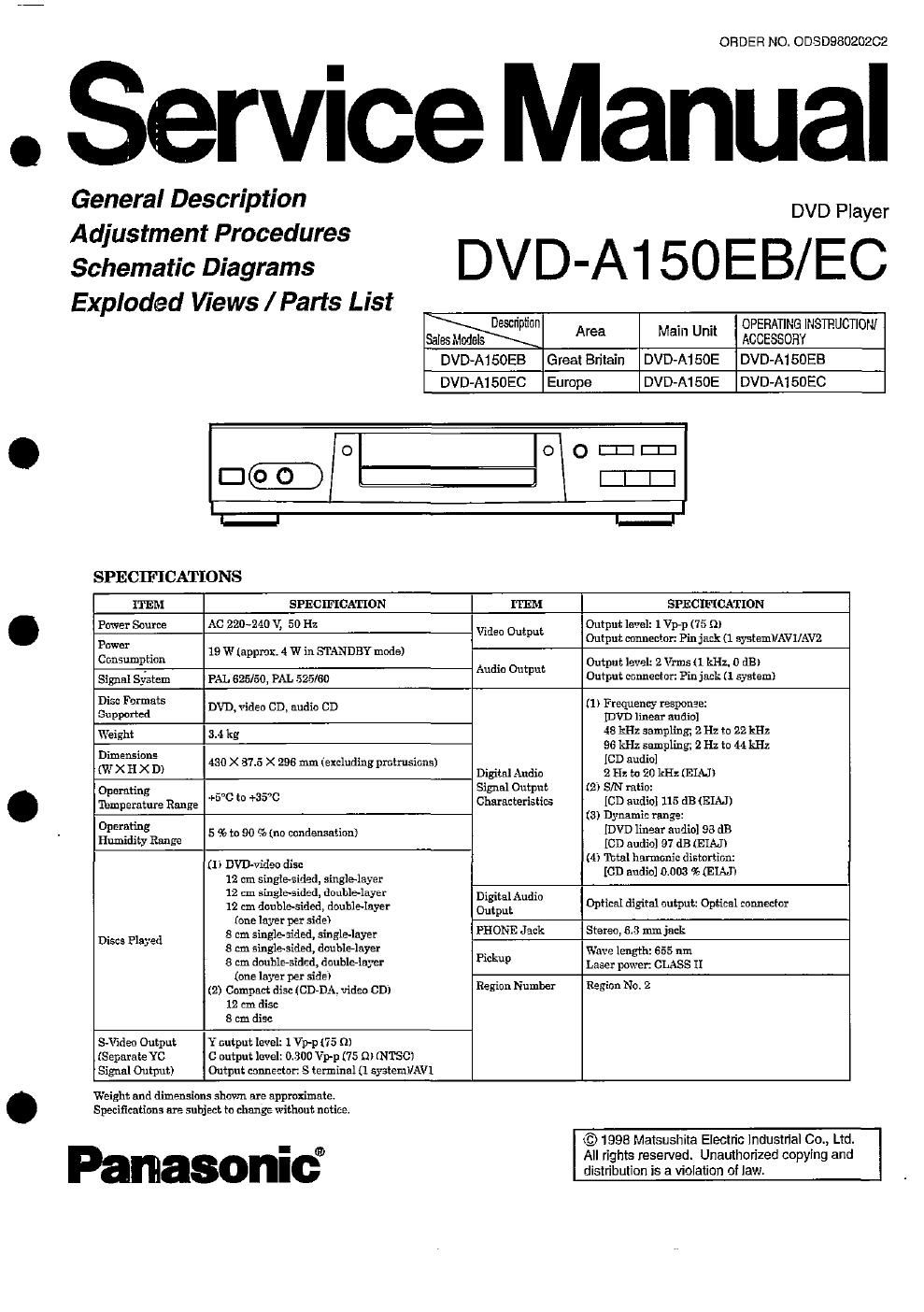
panasonic dvd a 150 service manual

Extracted text from panasonic dvd a 150 service manual (Ocr-read)


Page 2

AWARNING
This service information is designed for experienced repair technicians oniy and is not designed for use by the general public. It
does not contain warnings or cautions to advise non-technical individuals of potential dangers in attempting to service a product.
Products powered by electricity should be serviced or repaired only by experienced professional technicians. Any attempt to
service or repair the product or products dealt with in this service information by anyone else could result in serious injury or death.

INTRODUCHON

This service manual contains techinical information which will allow service personnels to understand and service this

model.

Section 1 presents you with some general information of features and controls, enabling you to become familiar with

each function.

Section 2 contributes to your mechanical and electrical adjustment as well disassembiy and replacement

procedures.

Section 3 contains schematic diagrams which give you detailed information such as wavefOIms, voltage data,

function e. t c.
Section 4 contains exploded views and parts list.

Please place orders using the pans list and not the drawing reference numbers.
If the circuit is changed or modified, this information will be followed by supplementary service manual to be filed with

CONTENTS

original service manual.

Safety Precautions ...................
Prevention of ESD to ES Devices
Precaution of Laser Diode .......

Handling Precautions fchraverse Deck
Self-Diagnosis Function for Service Number Display .
Service lnforrnation ..................................................

OPERATING INSTRUCTIONS
Control reference guide
Front panel display
Basic connection
Optional video co
Optional audio connec on
Remote control preparation.
Basic pyla .........................
Ralpid advance (Rapid reverse
Sti picture (Pause) ..................
Frame advance [DVDNideo CD]
Slow-motion play [DVD/Video CD] .. .
Enjoy video CDs with playback control Without usmg menus
[\fIdeo CD oniy .
Initial settings ..
Troubleshooting .
Disc handling and maIntenance

ADJUSTMENT PROCEDURES
How to Remove the Disc on the Tray in Trouble ..................... 2-
Disassembly, Reassembly, Replacement and Adjustment
procedures ..
1. Disassem ng and Reassembiing the Casing Part
1-1. Removing the Top Cover ..
1-2. Removing the Front Panel
143. Reassembling the Casing Parts
2. Disassembling and Reassembling the Loading Base
2-1. Removal of the Loading Base ...........................
2-2. Disassembling the Clamp Support Plate and
the Clamper
24!. Removing the

RUNNd-L

.-

Iii"?
summons

l

NNIPNN)

L£~J>

5. Removing the Loading Sec
2-6. Assembling the Loading Section Parts
7 Aseerrpbling the Traverse Unit

mmmmm

'P

NW.
<0 mmmmmwmmmmmm

Attac .ng the Clamp Support a
3. Replacing the Main Parts of the Travers-
3-1. Replacing the Laser Pick-up...
3-2. Replacing the Traverse Motor Uni
3-3. Replacing the Disc Motor .............
3-4 Disc Motor Assembly/Tentative Tilt Adjustment
3-5. Others .............................................
4. Printed Circuit Board Location and Wiring Connection
Diagram ..............................................................................

mmymmm

.

9

4-1 Printed Circuit Board Locatic
4- 2. Wiring Connection Diagram...
5. Dieassembly and Check Method of Pnntecl Circuit Board
Assembly (C. B. A ) ..................

6. Electrical Adjustment Procedures
6-1. TIlt Adjustment of Disc Motor
6-2. \fideo Output (Luminance Signal) Adju tment
G43. Wdeo Output (Chrominance Signal) Aciustrnent
7. Lubrication Information .

gerCgADIAGRAt/l/SCHEMATIC DIAGRAM/CIRCUIT BOARD
3-1. ABBREVIATIONS ......................................................... 3-1
BLOCK DIAGRAMS
3-2. Overall
3-3. Servo
3-4. Video .
3-5. Audio.
SCHEMATIC AGR MS
3-6. FEP and ADSC and Servo Section

(MAIN C.B.A. <1/5> ..................................
3-7. CDC and CPU SectIon (MAIN C.B.k <'215>)
3-8. CLOCK SYNC Section (MAIN C.B.A. <3/5>)
3-9. Audio-DAG Section (MAIN C.B.A. <4l5>)
3-10. AVDEC and \fIdec-DAC Se on

(MAIN ca. <5/5>)
3-11. AV Jack
3-12. Power Supply
3-13. AV21P ......
3-14. Operation and HP Jac
3-15. Interconnection ..........
CIRCUIT BOARD DIAGRAMS
3-16. Main C. B. A. (VEP9651 26) ..........
3-17. Po Ier Supply C. B. A. (VEP91 231 B)
3-18. AV Jack C. B. A. (VEP93303E).
319. AV21P C B A. NEPQSSOSC)
3-20. Operation C. B. A. (VEP9651 7E) and

(VEP94308A)
321. Mechanism IF . ,

(vxoosea). Loa 9 Motor 0B A. (VE.(BOO1) and

TIP SW U. (VEK8061) ..........

EXPLODED VIEWS 8:

REPLACEMENT PARTS LIST
4-1. Packing & Accessories Section
4-2. Casing Parts & Mechanism Section
4-3. Loading Mechanism Section .
4-4. Traverse Section ...............
4-5. Electrical Replacement Parts LIst


NNNI'VNN MN

.3-3