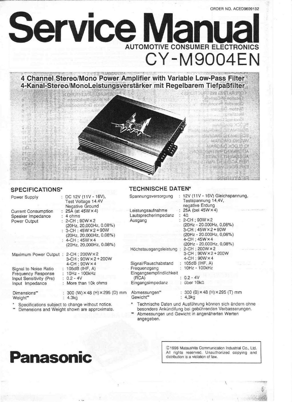
Panasonic cy m 9000 en service manual
This is the 24 pages manual for panasonic cy m 9000 en service manual.
Read or download the pdf for free. If you want to contribute, please upload pdfs to audioservicemanuals.wetransfer.com.
Extracted text from panasonic cy m 9000 en service manual (Ocr-read)
Page 2
' CY-M9004EN I
A WARNING
This service intonnation is designed Ior experienced repair behnicians onty and is not designed for use by the general public. 11
does not contain warnings or cautions to advise non-technical individuals at potential dangers in attempting to service a product.
Products powered by electricity shOUId be serviced or repaired only by experienced protessional technicians Any attempt to service
or repair the product or products dealt with in this service inionnation by anyone else could result in serious injury or death.
CONTENTS
Page
FEATURES ............................ 1
FUSE ................................. 1
DIMENSIONS ........................... 1
MAINTENANCE .................... 1
< OPERATING INSTRUCTIONS >
Location of Controls .................... 2
Operation Procedures ................... 2
System Diagram ....................... 3
Installation ........................... 3
Electrical Connection ................... 4
BLOCK DIAGRAM ..................... 8, 9
SCHEMATIC DIAGRAM (AMP) ............ 10
SCHEMATIC DIAGRAM (Power) ........... 11
WIRING DIAGRAM ...................... 12
IC BLOCK DIAGRAM ................... 13
ALIGNMENT INSTRUCTIONS ............. 13
ALIGNMENT POINTS ................... 13
REPLACEMENT PARTS LIST ......... 14~ 21
EXPLODED VIEW ...................... 22
FEATURES
0 90Wx4 Maximum Power Output.
0 Sub-woofer Cutoff Freqency Switching.
FUSE
INHALTSUERZEICHNIS
Seite
MERKMALE ............................ 1
SICHERUNG ........................... 1
PFLEGE ............................... 1
ABMESSUNGEN ........................ 1
< BEDIENUNG SANLEITUNG >
Lage der Kontrollfunktionen .............. 5
Grundiegende Ger'atebedienung ........... 5
Systemschema ........................ 6
Einbau .............................. 6
Elektrischer AnscthB ................... 7
BLOCK DIAGRAM ..................... 8. 9
SCHALTBILT (AMP) ..................... 10
SCHALTBILT (Power) .................... 11
VERDRHATUNG ....................... » 12
IC BLOCK DIAGRAM .................... 13
ABGLEICH ANLEITUNG .................. 13
ABGLEICHUNGSPUNKTE ................ 13
ERSATZTEILLISTE ................. 14~ 21
AUFGELOTE DARSTELLUNGS ............ 22
M ERKMALE
o 90W><4 Hochstausgangsleistung.
0 Umschaltung der Subwoofer-Trennfrequenz.
SICHERUNG
Be sure to use a fuse of the specified rating (30A)
when replacing a blown fuse. Fuse with higher
capacity ratings, use of any substitute, or connection
without a fuse may result in a fire hazard or damage to
the unit.
MAINTENANCE
To clean the exterior of this unit, use a soft cloth to
wipe the surface. Do not use benzine, thinner, or any
other type of solvents.
Als Ersatz fiir eine durchgebrannte Sicherung
unbedingt eine Sicherung mit dem vorgeschriebenen
Nennwert (30A) verwenden Durch den Gebrauoh von
Sicherung mit hdheren Nennwerten, von
Sicherungsersatzteilen oder durch den AnschluB ohne
Gebrauch einer Sicherung kann ein Brand oder
Gerateschaden verursacht werden.
PFLEGE
Zur Reinigung das aussere des Gerates mit einem
weichen Tuch abwischen. Auf keinen Fall Benzin.
Verdfinner oder irgendein anderes Losemittel
verwenden.
DIMENSIONS / ABMESSUNGEN