Optonica st 105 h service manual

This is the 27 pages manual for optonica st 105 h service manual.
Read or download the pdf for free. If you want to contribute, please upload pdfs to audioservicemanuals.wetransfer.com.

Page: 1 / 27
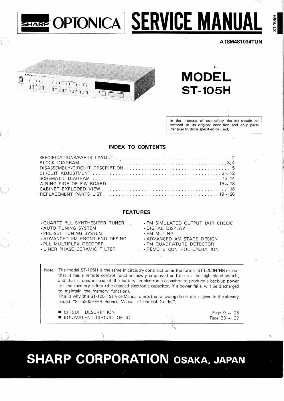
optonica st 105 h service manual

Extracted text from optonica st 105 h service manual (Ocr-read)


Page 1

@wromc/s. SERVICE MANUAL

ATSM481034TU N

ST-105H


MODEL

HTTI 7|

IT] Vi

iiiii ' . ..
- 3333222333] ST-105H
In the interests of user-safety the set should be
restored to its original condition and only parts
, identical to those specified be used. 3
I
INDEX TO CONTENTS 1i
SPECIFICATIONS/PARTS LAYOUT . ._ ..................................... 2 I
BLOCK DIAGRAM ................................................... 3,4 I
DISASSEMBLY/CIRCUIT DESCRIPTION .................................... 5
CIRCUIT ADJUSTMENT ............................................. 6~12 I
SCHEMATIC DIAGRAM ............................................. 13,14 I
, WIRING SIDE OF P.W. BOARD ....................................... 15~18
CABINET EXPLODED VIEW ............................................ I8 I
REPLACEMENT PARTS LIST ........................................ 19~26 I
I
FEATURES I
-QUARTZ PLL SYNTHESIZER TUNER -FM SIMULATED OUTPUT (AIR CHECK)
AUTO TUNING SYSTEM -D|GTAL DISPLAY I
- PRE-SET TUNING SYSTEM - FM MUTING I
-ADVANCED FM FRONT-END DESING -ADVANCED AM STAGE DESIGN
-PLL MULTIPLEX DECODER - FM QUADRATURE DETECTOR
~ LINER PHASE CERAMIC FILTER . ' REMOTE CONTROL OPERATION

Note: The model ST-lOBH is the same in circiutry construction as the former STeBZOOH/HB except
that it has a remote control function newly employed and disuses the high blend switch, I
and that it uses instead of the battery an electronic capacitor to produce a back-up power I
for the memory safety (the charged electronic capacitor, if a power fails, will be discharged
to maintain the memory function).
This is why this ST-IOBH Service Manual omits the, following descriptions given in the already
issued "ST-5200H/HB Service Manual (Technical Guide).

I CIRCUIT DESCRIPTION Page 9 ~ 25
I EQUIVALENT CIRCUIT OF IC Page 33 ~ 37

SHARP CORPORATION OSAKA, JAPAN

Page 2

SPECIFICATIONS

GENERAL DESCRIPTION

Power Source:
Circuit:

Power Consumption:
Semiconductors:

AC 110/220/240 V, 50/60 Hz
Superheterodyne and PLL synthesizer
tuning system, FM/MW/LW 3-band
tuner, multiplex FM stereo decorder,
FM muting, airecheck calibrator
15W

leMicrocomputer

1-L-SI (Large Scale Integrated Circuit)
9-ICs (Integrated Circuit)

1-FET (Dual Gate, MOS type)
2»FETs (Junction type)
60-Transistors

Frequency Response:
Image Rejection:

IF Rejection:
Selectivity:

30 to 15000 Hz 1 3 dB
75 dB (at 98 MHz)

75 dB (3
45 dB

(22.5 kHz deviation, i300 kHz)

Capture Ratio:
AM Suppression:
S/N:

Distortion:

Stereo Separation.
FM Output Voltage:

2.5 dB
50 dB

t98 MHz)

66 dB (40 kHz deviation)

Mono;
Stereo;

0.2%
0.3%

40 dB (at 1 kHz)

350 mV

(40 kHz deviation)

(SE-Diodes MW/LW

4 Variable capacitance diodes (for FM) Tuning range: MW; 522 ~ 1611 kHz
3 Variable capacitance diodes LW; 150~ 372 kHz
(for MW/LW) (F: 450 kHz

18 LEDs and I-LED Array unit
(for signal indicator)

Scan Frequency: 1 kHz (Manual Tuning)

9 kHz (Automatic Tuning)

Dimensions: Width; 430 mm Ouieting Sensitivity: MW; 350 pV/m
Height; 71 mm l_W; 350 uV/m
Depth: 298 mm Image Rejection: MW; 40 dB (at 999 kHz)
Weight; 3.4 kg LW; 30 dB (at 218 kHz)
IF Rejection: MW; 40 dB (at 999 kHz)
FM LW; 40 dB (at 218 kHz)
Tuning Range' 87,6 to 108 MHz Distortion: 15%

IF: 10.7 MHz Output Voltage: 200 mV (400 Hz, 30% Modulation)
Scan Frequency: 50 I Sensitivity: 1.3 uV (at S/N 26 dB,

40 kHz deviation, 75 ohms)
1.6 uV (at S/N 26 dB,
40 kHz deviation, 300 ohms)

Specifications are subject to change without prior notice. 1

PARTS LAYOUT

5 7 B 9
l
l
.iinunnnnnmn '13 r...)
14 I3 12 11 10 23
1. Power switch 12. Automatic tuning indicator
2. Air check indicator 13. Frequency input presetting button
3. FM mono/muting off indicator 14. Preset station memory button
4. Band indicator 15. Band selector button
5, Preset station memory indicator 16. FM mono/muting off button
6. Frequency input presetting indicator 17. Air check button
7. Signal strength indicator 18_ Power indicator
8. FM stereo indicator 19. FM Coaxial antenna socket (DIN 45 325 type)
9. Tuning frequency and band display 20, Remote control sockets
10. Frequency count up/down button 21. Output sockets
11,Automatic tuning button 22. Voltage selector

23. Antenna terminals

_2_