Onkyo TXSV 424 Service Manual

This is the 42 pages manual for Onkyo TXSV 424 Service Manual.
Read or download the pdf for free. If you want to contribute, please upload pdfs to audioservicemanuals.wetransfer.com.

Page: 1 / 42
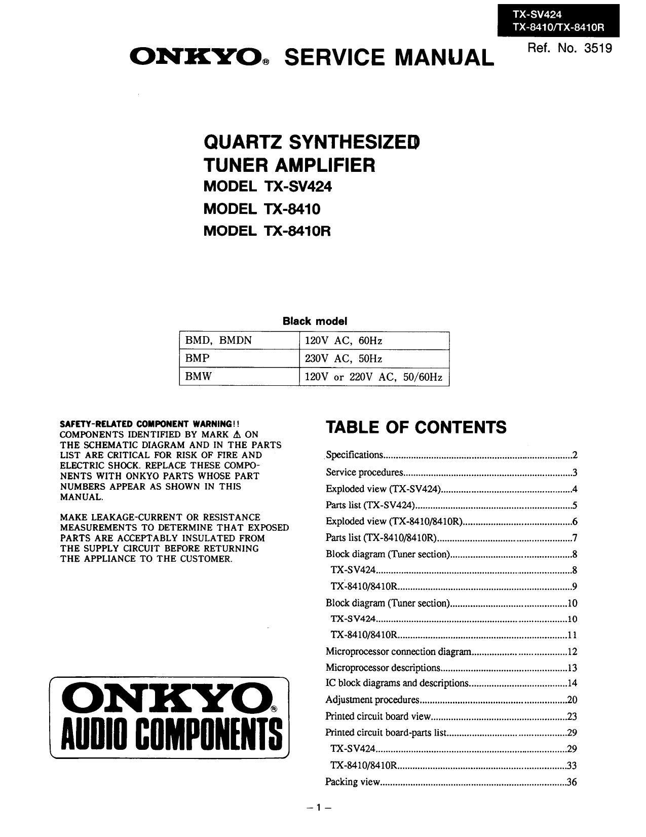
Onkyo TXSV 424 Service Manual

Extracted text from Onkyo TXSV 424 Service Manual (Ocr-read)


Page 1

TX-SV424
TX~8410/TX-8410R

ONKYO® SERVICE MANUAL Ref- N°- 3519

QUARTZ SYNTH ESIZED

TUNER AMPLIFIER
MODEL TX-SV424

MODEL TX-8410
MODEL TX-8410R

Black model

BMD, BMDN

120V AC, 60Hz

BMP

230V AC, 50Hz

BMW

120V or 220V AC, 50/60Hz

SAFETY-RELATED COMPONENT WARNING
COMPONENTS IDENTIFIED BY MARK A ON
THE SCHEMATIC DIAGRAM AND IN THE PARTS
LIST ARE CRITICAL FOR RISK OF FIRE AND
ELECTRIC SHOCK. REPLACE THESE COMPO-
NENTS WITH ONKYO PARTS WHOSE PART
NUMBERS APPEAR AS SHOWN IN THIS
MANUAL.

MAKE LEAKAGE-CURRENT OR RESISTANCE
MEASUREMENTS TO DETERMINE THAT EXPOSED
PARTS ARE ACCEPIABLY INSULATED FROM
THE SUPPLY CIRCUIT BEFORE RETURNING

THE APPLIANCE TO THE CUSTOMER.

ONKYO®
IIIIIIIII BflMPflNINIS

TABLE OF CONTENTS


Specifications ..........

Service procedures. .3
Exploded view (TX-SW24)"

Parts list ('I'X-SV424) .............................................................. 5

Exploded view (T X-84IO/8410R),
Parts list (IX-8410/8410R) ...........


Block diagram (Tuner section) ................................................ 8
TX-SV424 .........
mime/841011. .9
Block diagram (Tuner section ...10
TX-SV424 ........................................................................... 10
TX»8410/8410R.r..
Microprocessor connection diagram,
Microprocessor descriptions .................................................. 13
IC block diagrams and descriptions
Adjustment procedures ..................
Printed circuit board view ...................................................... 23
Printed circuit board-pans list

TX-SV424..
TX-8410/8410R.
Packing View .......................................................................... 36

_1_

Page 13

TX-SV424

TX-8410/TX-8410R

TERMINAL DESCRIPTION

Pin No. Function I/O Descriptlon
1"7 7G'lG 0 Grid control output pin. On at the high level.
3 VDD Power supply pin (+5V)
9 CL 0 Clock output pin. Connect to the terminals CK of function switch Q302, surround
mode switch 0606. electro volume Q671, digital delay 0651 and ILL IC Ql7l.
10 DATA 0 Data output pin. Connect to the terminals DATA of function switch Q302, surround
mode switch Q606, elecu'o volume 067 land digital delay.
11 PLL 0 Chip enable output pin for PLL 1C
13 SEL 0 Chip eneble output pin. Connect to the terminals ST of function switch Q3102,
surround mode switch 0606 electro volume Q67land digital delay.
15 VOLUP 0 Volume control output pin
16 VOLDOWN 0 Refer table 1.
17 WI 1 System reset input pin

20 AVSS Ground pin of AID converter

21 MODE I Initializim input of operation mode

22 BAND I Initializine input of band region

23 MODEl I Initializing input of operation mode

24 K4 I Operation key connection pin

25 K3 I Operation key connection pin

26 K2 I Operation key connection pin

27 K1 I Operation key connection pin

28 K0 I Operation key connection pin

29 AVDO Analogue power supply of A/D converter

30 AVREF Reference voltage input pin of AID converter

31 XTl Crystal connection pin for sub system clock resonator
32 XIZ Not used.

33 V55 Ground pin

34 X1 Resonator connection terminal for main system clock
35 X2 Connect the ceramic resonator 4.19MHz.

36 TMUT 0 Muting output pin for tuner section

38 SMUT 0 Muting output pin for amplifier section
40 RELAY 0 Relay control pin for speaker

41 POWER 0 Power source control output pin

42 W 0 System code output pin

43 RDSDATA I Data input pin from RDS decoder p PD1346CS

43 SYSIN I System code input pin

44 W I Clock input pin from RDS decoder [C u PD1346CS
45 PO-FF I Power stoppage detector input pin

47 m I Remote control signal input pin

48 1C Internal connection pin. Connect to the ground terminal.
49 PROTECT 1 Detector input pin of protection circuit. H:On

50 STTY/RECV O Stand-by and received indicator output pin

52 VDD Power supply pin (+5V)

53 TWO I Detector input pin of FM stereo broadcast
54 SD I Detector input pin of broadcast more than muting level
55 m} I Detector input pin of RDS broadcast. L:RDS broadcast
56 RFIN I RF mode input pin. Local at the low level.
5770 Pv'Ic 0 Segment output pins. On at the hi gh level.
71 VLOAD I Pull»dcvm resistor connection pin of controller and driver of FL.
7275 Pd'la 0 Segment output pins. On at the high level.
76'80 12G'BG 0 Grid control output pin. On at the high level.
Operation #39 #40
VOLUME UP H L
VOLUME DOWN L H
STOP 1-1 H
Table 1

-13_