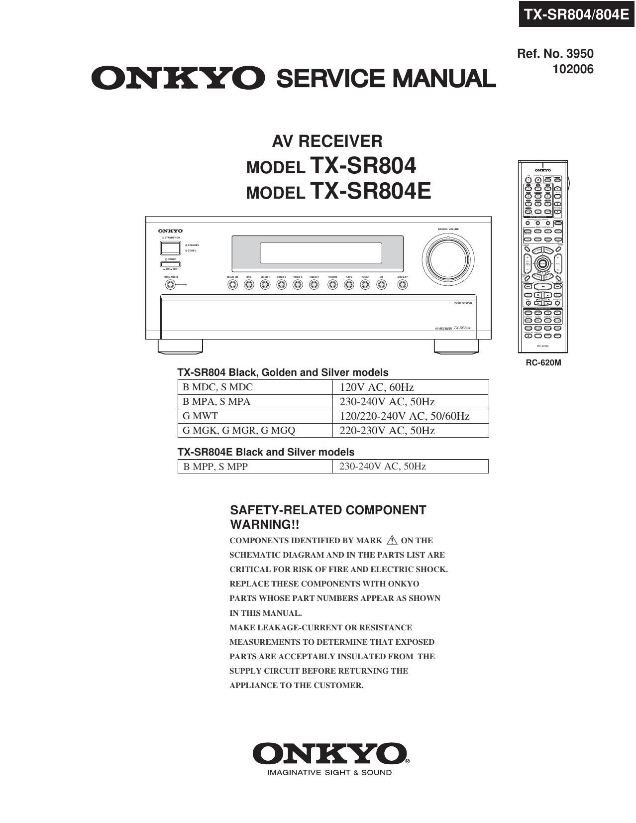
Onkyo TXSR 804 Service Manual
This is the 237 pages manual for Onkyo TXSR 804 Service Manual.
Read or download the pdf for free. If you want to contribute, please upload pdfs to audioservicemanuals.wetransfer.com.
Extracted text from Onkyo TXSR 804 Service Manual (Ocr-read)
Page 1
ONKYO SERVICE MANUAL
AV RECEIVER
MODEL TX-SR804
MODEL TX-SR804E
oNxYo
E
©@@@@@@@@@ (95 K
TX-SR804/804E
Ref. No. 3950
102006
TX-SR804 Black, Golden and Silver models
B MDC, S MDC 120V AC, ()OHZ
B MPA, S MPA 230»24OV AC, SOHZ
G MWT 120/220-240V AC, 50/60Hz
G MGK, G MGR, G MGQ 220-230V AC, SOHZ
TX-SR804E Black and Silver models
l B MPP, s MPP l 230-240v AC, 50m
SAFETY-RELATED COMPONENT
WARNING ! !
COMPONENTS IDENTIFIED BY MARK & ON THE
SCHEMATIC DIAGRAM AND IN THE PARTS LIST ARE
CRITICAL FOR RISK OF FIRE AND ELECTRIC SHOCK.
REPLACE THESE COMPONENTS WITH ONKYO
PARTS WHOSE PART NUMBERS APPEAR AS SHOWN
IN THIS MANUAL.
MAKE LEAKAGE-CURRENT OR RESISTANCE
MEASUREMENTS TO DETERMINE THAT EXPOSED
PARTS ARE ACCEPTABLY INSULATED FROM THE
SUPPLY CIRCUIT BEFORE RETURNING THE
APPLIANCE TO THE CUSTOMER.
ONKYO.
IMAGINATIVE SIGHT & SOUND
RC-SZUM
Page 2
R804/804E
SERVICE PROCEDURE
1. Replacing the fuses
EE This symbol located near the fuse indicates that the
fuse used is show operating type, For continued protection against
fire hazard, replace with same type fuse, For fuse rating, refer to
the marking adjacent to the symbol.
EE Ce symbole indique que le fusible utilise est e lent.
Pour une protection permanente, n'utiliser que des fusibles de meme
type. Ce demier est indique la qu 1e present symbol est apposre.
REF NO. PART NAME DESCRIPTION PART NO. REMARKS
F901 FUSE 10A»UL/T-233 25233OGR !,
F901 FUSE 6.3A-SE-EAK 252079GR !,
F902 FUSE 6.3AASE»EAK 252079GR !,
F903 FUSE 5A-UL/T-233 252326GR !,
F903 FUSE 2.5ASE-EAK 252075012 !,
F931 FUSE 1.6A»SE7EAK 252073GR !
F932 FUSE 1.6A»SEAEAK 25207ZGR !
F95] FUSE 6.3A-SEAEAK 252079GR l
F952 FUSE 6.3A-SE-EAK 25207QGR !
F6901 FUSE lZA-TUL-ZSOV 2523010R !
F6902 FUSE l2A-TULA250V 252301GR !
2. To initialize the unit
1. Press and hold down VIDEO 1 button, then press STANDBY/ON button when the unit is Power on.
2. After " Clear " is displayed, the preset memory and each mode stored in the memory are initialized and will
retum to the factory settings, and turn to Standby mode.
3. Safety check out
(U.S.A. model only)
After correcting the original service problem, perform the following safety check before releasing the unit to
the customer.
Leakage current Check
Measure the leakage current to a known earth ground (water pipe or conduct etc.) by connecting a leakage current
tester between the earth ground and exposed metal parts of the unit (input/output ground terminals, screw heads or
metal overlays etc.).
Plug the power supply cord directly into a lZOVac 60Hz wall socket and turn STANDBY button on.
Any current measured must not exceed 0.5mA.
4. Memory Backup
This model uses a battery-less memory backup system in order to retain radio presets and other settings
when it's unplugged or in the case of a power failure.
Although no batteries are required, the unit must be plugged into an AC outlet in order to charge the
backup system. Once it has been charged, the unit will retain the settings for several weeks,
although this depends on the environment and will be shorter in humid climates.
Page 5
-SFI804/804E
OPERATION CHECK-3
CONTROL OF POWER SUPPLY (SPEAKER OUTPUT SENSOR AND THERMAL DETECTOR)
[When]
1. Exchange power transistors (Q6050 » Q6056, Q6060 - Q6066).
2. Exchange power amplifier PC board ass'y (NAAF-8678, NAAF-8682).
3. Exchange thermal sensor PC board ass y (NAETC78680).
[Procedure]
Output Sensor
1. Press and hold down CD button, then press STANDBY/ON button while the unit is Power ON.
" Test - 7 " will be displayed only for 5 seconds.
Test
*7 Blinks
2. Press VIDEO 3 button while " TBSI * 7 " is displayed.
The unit will be in the state of " Test-4-OO ".
Test - 4-00
3. Repeatedly press TONE+ button until " Test-4-36 " is displayed.
Te St - 4 - 3 6
4. At this time, confirm that the red characters of " FM STEREO " is displayed.
And, confirm that the relays (RL6901 and RL6902) are turned off in 2 or 3 seconds. (FL+FR+C+SL check)
FM STEREO
Test - 4-36
5. Press TONE+ button and confirm that the red characters of " FM STEREO " is displayed and
the relays (RL6901 and RL6902) are turned off in 2 or 3 seconds as well as 4. (C+SR+SBL+SBR check)
. FM STEREO
Test - 4-37
6. Press STANDBY/ON button.
Turn off
Clear ->
Thermal Detector
1. Press and hold down DISPLAY button, then press STANDBY button when the unit is power ON.
The main microprocessor version will be displayed only for 3 seconds.
Ver.1.01/06920a
2. Press TONE button while the version is displayed, then the temperature will be displayed.
T: 25°C/ 77°F
3. Confirm that the displayed temperature is within +/-20 °C from the ambient temperatures.
4. Press STANDBY/ON button.
Turn off
Clear ->
Page 42
TX SR804/804E
A l B C D E F G
SCHEMATIC DIAGRAM-8 (SD-8)
POWER SUPPLY SECTION
NAPS-9000
ICL3221 E
05501
POWER SUPPLY PC BOARD
P5501
TI OUT
FORCEDN C2«
TI IN O27
252TxD R S 2 32
- MWT Iype Only
2 2(1/2W) 155155
R951 D951
232RxD
R1OUT
D952
(1/2W) 155153
1
A m
3 3 10
§ (1951 T217505 9 u: 2:
F951 0 1 I o 5VDSP a i at
F 0 5ND 7 z 0 12V TRIGGER
5 5A LZSOV g a w
a 5 .9 OUT ZONE 2
UJ A 7777777
E E 5
1;: 32+
E O D951 2
O u. RNINAOUS 1
11% 52_ m
0 < D952 E
I- ,- - -- --------- a:
E XM POWER MDc lype only _I RN1NAnua n 2351240
2SA1453 E 05502
022 5
mm) a
F952 1 a:
5 5A LzsuV szcsa 3
co M
(II) C]
D- 'T
R: < (:1
3 z (I)
O
I-
53 53
m m
a. m
«I «.
m1 8' 8 P5505" I
1 6A L25uV mg 3 RN1202 05505 IR IN
§g 8 0958 RN1202
E m
D:
m g 8% IR OUT
m E GRAV 8 32
g E): N 2 GNDA WHITE K
O u. g GRAV R946 Ogss
CL % a BLUE (132W) stIasa
O FLAczA BLuE
'- E
- A
0950
2sc1ms
F932
1 SA LZSOV 22
9957 (112w) 25A955V
RN1Nmus R963 0254 55
In
m 1::
=1 h L
WI 5 g; _ ZONE 2
ASVDSP 4 £9 LINE OUT
NP 3 g g R
5353 2 z
1 O
,_
SDF :XY is Short (or Shoemafic Diagramrx and
each Sockets locallon. X=Alo H, to 5
~ THE COMPONENTS IDENTIFIED BV MARKAARE CRITICAL FOR SAFETV
REPLACE ONLV WITH PART NUMBER SPECIFIED
. VOLTAGE (MEASURED WITH VOLTMETER) (:15 Do VOLTAGE (N0 ILIPUT SIGNA 1219595
~ ALL PNP TRANSISTORS ARE EQUIVALENT TO 2SAIOI erR UNLESS OTHERWISE NOTED TO NAAR-8997
. ALL NPN TRANSISTORS ARE EQUIVALENT TO ESCIBISVGR UNLESS OTHERWISE NOTED SD-4:H2
~ ALL DIODES ARE EQUIVALENT TO ISSm UNLESS OTHERWISE NOTED
. ELECTROLVTIC cAPAcITORS< 43: )ARE IN UFWV
~ ALL CAPACITORS ARE IN pFISDWV UNLESS OTHERWISE NOTED
EX) 030 3pF 330 SBDF 3317 asupF 3337 o DSGUF
~ ALL RESISTORS ARE IN OHMS IIAWATTS UNLESS OTHERWISE NOTED
. THE THICK LINES ON PC BOARD ARE THE PRINTING SIDE OF THE PARTS
EX) -/ PRINTING SIDE
~ CIRCUIT IS SUEJECTTD CHANGE FOR IMPROVEMENT
Page 102
R804 E
IC BLOCK DIAGRAMS AND TERMINAL DESCRIPTIONS -8
0201: CS494003 (DSP)
TERMINAL DESCRIPTION (3/3)
PIN NO- TERMINAL NAME/DESCIPTION
97 HDATA5, GPIOS: DSPC Bidirectional Data Bus, General Purpose l/O
98 SCLK1: Audio Output Bit Clocszidirectional digitaleaudio output bit clock for AUDATA4, to AUDATA7.
As an output, SCLK1 can provide 32 fs, 64 fs, 128 fs, 256 fs, or 512 fs frequencies and is synchronous to MCLK.
99 MCLK: Bidirectional master audio clock. As an output, MCLK provides a low jitter oversampling clock.
100 VDD2: 2.5V supply voltage.
101 VSS2: 2.5V ground.
102 AUDATA4, GPIOZB: Digital Audio Output 4, General Purpose |/O.PCM digitalraudio data output.
103 HDATA4, GPIO4: DSPC Bidirectional Data Bus, General Purpose l/O
104 SCLKO: Audio Output Bit Clock;Bidirectional digitalraudio output bit clock for AUDATAO, to AUDATAS.
105 HDATA3, GPIO3: DSPC Bidirectional Data Bus, General Purpose l/O
106 AUDATA3, XMT958A: Digital Audio Output 3, S/PDIF Transmitter
107 AUDATA2: PCM digitalraudio data output.
108 LRCLKO: Audio Output Sample Rate Clock
109 AUDATAI: PCM digitalraudio data output.
110 AUDATAO: PCM digitaleaudio data output.
111 CMPCLK, FSCLKN2: PCM Audio Input Bit Clock:Digitale audio bit clock input.
112 HDATA2, GPIO2: DSPC Bidirectional Data Bus, General Purpose l/O
113 VSSS: 2.5V ground.
114 VDD3: 2.5V supply voltage.
115 HDATA1, GPIOt: DSPC Bidirectional Data Bus, General Purpose l/O
116 HDATAO, GPIOO: DSPC Bidirectional Data Bus, General Purpose l/O
117 CMPREQ, FLRCLKN2: PCM audio input request
118 CMPDAT, FSDATAN2: Digitaleaudio data input that can accept either 1 compressed line or 2 channels of PCM data.
119 FLRCLKNt: Digitaleaudio frame clock input.
120 WR, DS, GPIOtO: Host Write Strobe, Host Data Strobe, General Purpose |/O
121 RD, R/W, GPIOf1: Host Parallel Output Enable, Host Parallel R/W, General Purpose l/O
122 PLLVSS : PLL Ground Voltage
123 FILT2: PhaseeLocked Loop Filter.Connects to an external filter for the phaseelocked loop.
124 FILT1: PhaserLocked Loop Filter.Connects to an external filter for the phaserlocked loop.
125 PLLVDD: 2.5V PLL supply voltage.
126 XTALO: Crystal oscillator output.
127 CLKIN, XTALI: External Clock input / Crystal Oscillator input:12MHz crystal oscillator is connected.
128 CLKSEL: DSP Clock select input
129 CS, GPIOQ: Host Parallel Chip Select, General Purpose l/O
130 A0, GPIO13: Host Address Bit 0, General Purpose l/O
131 FSDATAN1: Digitalraudio data input can accept from one compressed line or 2 channels of PCM data.
132 VDD4: 2.5V supply voltage.
133 VSS4: 2.5V ground.
134 FSCLKN1, STCCLKZ: Digital audio bit clock input.
135 $03: Host Serial SPI Chip Select:SPl mode activeelow chipeselect input signal.
136 SCDIN: SPI Serial Control Data Inputzln SPI mode this pin serves as the data input pin.
137 VSSS: 2.5V ground.
138 VDD5: 2.5V supply voltage.
139 A1, GPIO12: Host Address Bit 1, General Purpose l/O
140 SCDOUT, SCDIO: Serial Control Port Data Input and Outputzln SPI mode this pin serves as the data output pin.
141 HINBSY, GPIOB: Input host Message Status, General Purpose l/O. This pin is indicates that serial
or parallel communication data written to the DSP has not been read yet.
142 SCCLK: This pin serves as the serial SPI clock input.
143 UHSZ, CSiouT, GPIO17: Mode Select Bit 2, External Serial Memory Chip Select,General Purpose l/O
144 RESET: Master Reset InputzAsynchronous activerlow master reset input.
Page 121
TX-SR804/804E
IC BLOCK DIAGRAMS AND TERMINAL DESCRIPTIONS -27
08001 : Sll504 (HP Video Converter)
TERMINAL DESCRIPTION (1/4)
Signal Group Signal Name Notes Type Description
Video Input VidInData[9:2] 5V In Multiplexed Video Input Data (ITU»FI BT.656,
8-bit & H/V syncs formats); Y (Iuma) Video
Input Data (16-bit & H/V syncs format).
VidInData[19:12] 5V/PD In Chroma Video Input Data (16-bit & H/V syncs
(HostData[15:8]) format only). See Host Interface pin list for
pin functions when not used for video input.
VS 5V/PD In Vertical Sync input (8/16-bit & H/V syncs
(HostData[7]) format only). See Host Interface pin list for
pin function when not used for video input.
HS 5V/PD In Horizontal Sync input (8/16-bit & H/V syncs
(HostData[6]) format only). See Host Interface pin list for
pin function when not used for video input.
VidInClk 5V In Video Input Clock, 27.0 MHz
Video Output Red_Cr[9:O] Out Red Data (RGB output mode);
Cr Data (YCer output mode)
Green_Y[9:0] Out Green Data (RGB output mode);
Y Data (YCer output mode)
Blue_Cb[9:O] Out Blue Data (RGB output mode);
Cb Data (YCer output mode)
/HSync Out Horizontal Sync
/VSync Out Vertical Sync
/CSync Out Composite Sync
/CBlank Out Composite Blank
LCDPern Out LCD Power Enable
VidOutCIk Out Video Output Clock, 36, 27 or 24 MHz
CIk48M 5V InOut 48 MHz Clock. Normally, this pin is a no-
connect, outputting an internal PLL-generated
48.0 MHz clock and receiving that same clock
through its input buffer. To bypass the PLL,
set /BprLLCIk48M = O, and supply a 48.0
MHz clock to the CIk48M pin.