Onkyo TXSR 804 E Service Manual

This is the 237 pages manual for Onkyo TXSR 804 E Service Manual.
Read or download the pdf for free. If you want to contribute, please upload pdfs to audioservicemanuals.wetransfer.com.

Page: 1 / 237
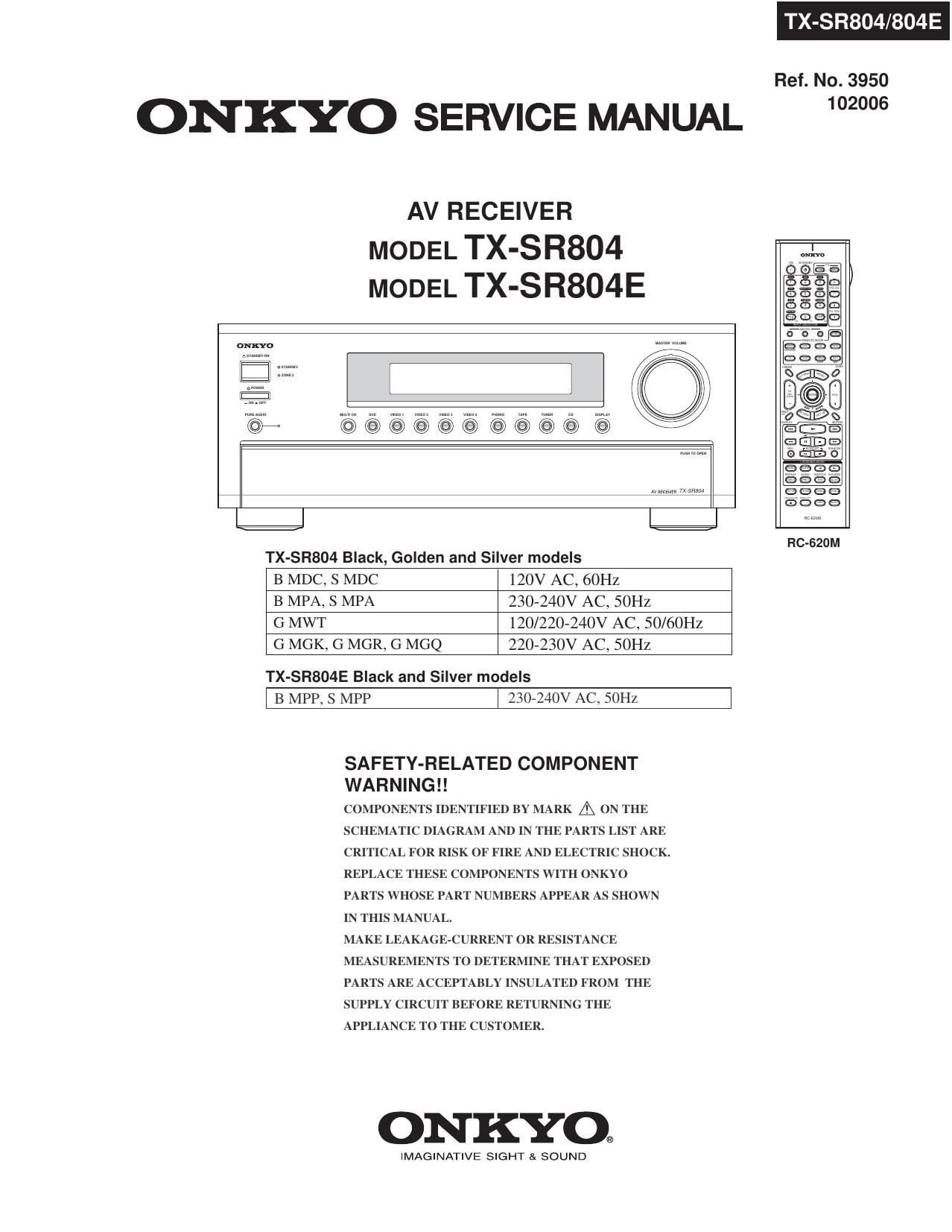
Onkyo TXSR 804 E Service Manual

Extracted text from Onkyo TXSR 804 E Service Manual (Ocr-read)


Page 1

ONKYO SERVICE MANUAL

AV RECEIVER

MODEL TX-SR804
MODEL TX-SR804E

oNxYo

E

©@@@@@@@@@ (95 K

TX-SR804/804E

Ref. No. 3950
102006

TX-SR804 Black, Golden and Silver models

B MDC, S MDC 120V AC, ()OHZ

B MPA, S MPA 230»24OV AC, SOHZ

G MWT 120/220-240V AC, 50/60Hz
G MGK, G MGR, G MGQ 220-230V AC, SOHZ

TX-SR804E Black and Silver models

l B MPP, s MPP l 230-240v AC, 50m

SAFETY-RELATED COMPONENT
WARNING ! !

COMPONENTS IDENTIFIED BY MARK & ON THE
SCHEMATIC DIAGRAM AND IN THE PARTS LIST ARE
CRITICAL FOR RISK OF FIRE AND ELECTRIC SHOCK.
REPLACE THESE COMPONENTS WITH ONKYO
PARTS WHOSE PART NUMBERS APPEAR AS SHOWN
IN THIS MANUAL.

MAKE LEAKAGE-CURRENT OR RESISTANCE
MEASUREMENTS TO DETERMINE THAT EXPOSED
PARTS ARE ACCEPTABLY INSULATED FROM THE
SUPPLY CIRCUIT BEFORE RETURNING THE
APPLIANCE TO THE CUSTOMER.

ONKYO.

IMAGINATIVE SIGHT & SOUND

RC-SZUM

Page 2

R804/804E

SERVICE PROCEDURE

1. Replacing the fuses

EE This symbol located near the fuse indicates that the

fuse used is show operating type, For continued protection against
fire hazard, replace with same type fuse, For fuse rating, refer to
the marking adjacent to the symbol.

EE Ce symbole indique que le fusible utilise est e lent.

Pour une protection permanente, n'utiliser que des fusibles de meme
type. Ce demier est indique la qu 1e present symbol est apposre.


: TX-SR804 Canadian model : TX~SR804 Korean model
: TX-SR804 Australian model : TX-SR804 Hong kong model
: TX-SR804E European model : TX-SR804 Chinese model
: TX-SR804 World wide model

REF NO. PART NAME DESCRIPTION PART NO. REMARKS

F901 FUSE 10A»UL/T-233 25233OGR !,

F901 FUSE 6.3A-SE-EAK 252079GR !,
F902 FUSE 6.3AASE»EAK 252079GR !,

F903 FUSE 5A-UL/T-233 252326GR !,

F903 FUSE 2.5ASE-EAK 252075012 !,
F931 FUSE 1.6A»SE7EAK 252073GR !

F932 FUSE 1.6A»SEAEAK 25207ZGR !

F95] FUSE 6.3A-SEAEAK 252079GR l

F952 FUSE 6.3A-SE-EAK 25207QGR !

F6901 FUSE lZA-TUL-ZSOV 2523010R !

F6902 FUSE l2A-TULA250V 252301GR !

2. To initialize the unit

1. Press and hold down VIDEO 1 button, then press STANDBY/ON button when the unit is Power on.
2. After " Clear " is displayed, the preset memory and each mode stored in the memory are initialized and will
retum to the factory settings, and turn to Standby mode.

3. Safety check out
(U.S.A. model only)
After correcting the original service problem, perform the following safety check before releasing the unit to
the customer.

Leakage current Check

Measure the leakage current to a known earth ground (water pipe or conduct etc.) by connecting a leakage current
tester between the earth ground and exposed metal parts of the unit (input/output ground terminals, screw heads or
metal overlays etc.).

Plug the power supply cord directly into a lZOVac 60Hz wall socket and turn STANDBY button on.

Any current measured must not exceed 0.5mA.

4. Memory Backup
This model uses a battery-less memory backup system in order to retain radio presets and other settings
when it's unplugged or in the case of a power failure.
Although no batteries are required, the unit must be plugged into an AC outlet in order to charge the
backup system. Once it has been charged, the unit will retain the settings for several weeks,
although this depends on the environment and will be shorter in humid climates.

Page 102

R804 E

IC BLOCK DIAGRAMS AND TERMINAL DESCRIPTIONS -8
0201: CS494003 (DSP)

TERMINAL DESCRIPTION (3/3)

PIN NO- TERMINAL NAME/DESCIPTION
97 HDATA5, GPIOS: DSPC Bidirectional Data Bus, General Purpose l/O
98 SCLK1: Audio Output Bit Clocszidirectional digitaleaudio output bit clock for AUDATA4, to AUDATA7.
As an output, SCLK1 can provide 32 fs, 64 fs, 128 fs, 256 fs, or 512 fs frequencies and is synchronous to MCLK.
99 MCLK: Bidirectional master audio clock. As an output, MCLK provides a low jitter oversampling clock.

100 VDD2: 2.5V supply voltage.

101 VSS2: 2.5V ground.

102 AUDATA4, GPIOZB: Digital Audio Output 4, General Purpose |/O.PCM digitalraudio data output.
103 HDATA4, GPIO4: DSPC Bidirectional Data Bus, General Purpose l/O

104 SCLKO: Audio Output Bit Clock;Bidirectional digitalraudio output bit clock for AUDATAO, to AUDATAS.
105 HDATA3, GPIO3: DSPC Bidirectional Data Bus, General Purpose l/O

106 AUDATA3, XMT958A: Digital Audio Output 3, S/PDIF Transmitter

107 AUDATA2: PCM digitalraudio data output.

108 LRCLKO: Audio Output Sample Rate Clock

109 AUDATAI: PCM digitalraudio data output.

110 AUDATAO: PCM digitaleaudio data output.

111 CMPCLK, FSCLKN2: PCM Audio Input Bit Clock:Digitale audio bit clock input.

112 HDATA2, GPIO2: DSPC Bidirectional Data Bus, General Purpose l/O

113 VSSS: 2.5V ground.

114 VDD3: 2.5V supply voltage.

115 HDATA1, GPIOt: DSPC Bidirectional Data Bus, General Purpose l/O

116 HDATAO, GPIOO: DSPC Bidirectional Data Bus, General Purpose l/O

117 CMPREQ, FLRCLKN2: PCM audio input request

118 CMPDAT, FSDATAN2: Digitaleaudio data input that can accept either 1 compressed line or 2 channels of PCM data.
119 FLRCLKNt: Digitaleaudio frame clock input.

120 WR, DS, GPIOtO: Host Write Strobe, Host Data Strobe, General Purpose |/O

121 RD, R/W, GPIOf1: Host Parallel Output Enable, Host Parallel R/W, General Purpose l/O
122 PLLVSS : PLL Ground Voltage

123 FILT2: PhaseeLocked Loop Filter.Connects to an external filter for the phaseelocked loop.
124 FILT1: PhaserLocked Loop Filter.Connects to an external filter for the phaserlocked loop.

125 PLLVDD: 2.5V PLL supply voltage.
126 XTALO: Crystal oscillator output.
127 CLKIN, XTALI: External Clock input / Crystal Oscillator input:12MHz crystal oscillator is connected.
128 CLKSEL: DSP Clock select input
129 CS, GPIOQ: Host Parallel Chip Select, General Purpose l/O
130 A0, GPIO13: Host Address Bit 0, General Purpose l/O
131 FSDATAN1: Digitalraudio data input can accept from one compressed line or 2 channels of PCM data.
132 VDD4: 2.5V supply voltage.
133 VSS4: 2.5V ground.
134 FSCLKN1, STCCLKZ: Digital audio bit clock input.
135 $03: Host Serial SPI Chip Select:SPl mode activeelow chipeselect input signal.
136 SCDIN: SPI Serial Control Data Inputzln SPI mode this pin serves as the data input pin.
137 VSSS: 2.5V ground.
138 VDD5: 2.5V supply voltage.
139 A1, GPIO12: Host Address Bit 1, General Purpose l/O
140 SCDOUT, SCDIO: Serial Control Port Data Input and Outputzln SPI mode this pin serves as the data output pin.
141 HINBSY, GPIOB: Input host Message Status, General Purpose l/O. This pin is indicates that serial
or parallel communication data written to the DSP has not been read yet.
142 SCCLK: This pin serves as the serial SPI clock input.
143 UHSZ, CSiouT, GPIO17: Mode Select Bit 2, External Serial Memory Chip Select,General Purpose l/O
144 RESET: Master Reset InputzAsynchronous activerlow master reset input.

Page 122

TX R804/804E

IC BLOCK DIAGRAMS AND TERMINAL DESCRIPTIONS -28

08001 : Sll504 (HP Video Converter)

TERMINAL DESCRIPTION (2/4)

Signal Group Signal Name

Notes

Type

Description

Video Output
(continued)

/BprLLC|k48M

PU

Bypass PLL for CIk48M. Normally, this pin is
a no-connect, and the internal pullup ensures
that the PLL is enabled. To bypass the PLL,
set /BprLLCIk48M = O, and supply a 48.0
MHZ clock to the C|k48M pin.

Clk54_72M

5V

InOut

54 or 72 MHz Clock. Normally, this pin is a
no»connect, outputting an internal PLL-
generated 54.0 MHz or 72.0 MHz clock and
receiving that same clock through its input
buffer. To bypass the PLL, set
/BprLLC|k54_72M = 0, and supply a 54.0
or 72.0 MHz clock to the Clk54_72M pin. »

/BprLLC|k54_72M

5V/PU

Bypass PLL for Clk54_72M. Normally, this
pin is a no-connect, and the internal pullup
ensures that the PLL is enabled. To bypass
the PLL, set /BprLLCIk54_72M = 0, and
supply a 54.0 MHz or 72.0 MHz clock to the
Clk54_72M pin.

Audio/Video
Synchronization

SDIn

5V/PD

Serial Digital Audio Input Data. See Audio/
Video Synchronization section of Functional
Description for audio formats supported.

WSIn

5V/PD

Serial Digital Audio Input Word Select. See
Audio/Video Synchronization section for audio
formats supported.

SCKIn

5V/PD

Serial Digital Audio Input Clock. Frequency
range of clock is 1.411 to 6.144 MHz. See
Audio/Video Synchronization section for
audio formats supported.

SDOut

Out

Serial Digital Audio Output Data. Audio
output follows audio input, with a delay equal
to that of the video processing pipeline.

WSOut

Out

Serial Digital Audio Output Word Select.
Audio output follows audio input, with a delay
equal to that of the video processing pipeline.

SCKOut

5V/PD

Serial Digital Audio Output Clock. Same
frequency as SCKIn. SDOut and WSOut are
generated from SCKOut. See Audio/Video
Synchronization section for more details on
on audio clocking.

Page 151

FIRMWARE UPDATE -2

Main Microprocessor Update Procedure

1

2
3
4
5

. Douwnload "flastaiexezip" to the PC and unzip. "FlashStaexe" will be created.

. Download the latest ".mot" and ".id" files for TX-SR804 to the same folder as the unzipped file of l.
. Download "Flash Writer M16 Manual.pdf to the PC and open it.

. Power on the unit and confirm that thejig is connected between PC and the unit.

. According to the Manual, start "FlashStaexe" to update the unit. MCU Type is Ml6C/20 62.

It takes about 5 minutes.

. After it ends, click "Exit button to end "FlastSta.exe".

. Turn off the main power switch or pull the power cord off the wall socket.

Pay attention that pushing STANDBY/ON button to power off is not perfect.

. Remove the jig from the unit and power on the unit again. Confirm the new version number.

DSP and Vide(HDMl) Update Procedure

1.

2

Make a folder in the PC or on desktop, which name is "UpdateLSR804" for example.

. Save the latest files "Update.exe" and "firmwarezip" in the folder above or on desktop.

. Unzip "firmwarezip" and confirm that "firmware" folder is created in "UpdateriSR804" folder.

And confirm that the following 4 programs are created in SR804" folder under firmware" folder.
fdist.fdf
FW804.dcf
DSP7803705Y28As28
674HDM16X03Amot

. Power on the unit and confirm thejig is connected between the PC and the unit.

. According to the peocedure of previous page, display DSP version on FL, and press ENTER button to display

"DSP PM Update", which is DSP firmware update mode.

DSP F/W Update

. Double click "Update.exe" on the PC. The following window will apear.

. Uudatrv _

00M FuvtQ) COM Put Spud

finww 3.5., gm" uxvvmxtvxtm'xxvymxxtw r m Vfibb
um rn / Flelljn

mum«mmmummummmmmm-xm

Po» Bead vacate Mud:
Vivien Update Dw Under:

S-TART

A

MmmlSend '-

. Click "Video Update" button for Video(HDMI) microprocessor update, or click "Dsp Update" button for DSP

microprocessor update. The update takes about 5 minutes each.

. After the update ends, turn off the unit's main power switch or pull the power cord off the wall socket.

. Remove thejig from the unit and power on the unit again. Confirm the new version number.