Onkyo TXNR 535 Service Manual
This is the 108 pages manual for Onkyo TXNR 535 Service Manual.
Read or download the pdf for free. If you want to contribute, please upload pdfs to audioservicemanuals.wetransfer.com.
Extracted text from Onkyo TXNR 535 Service Manual (Ocr-read)
Page 1
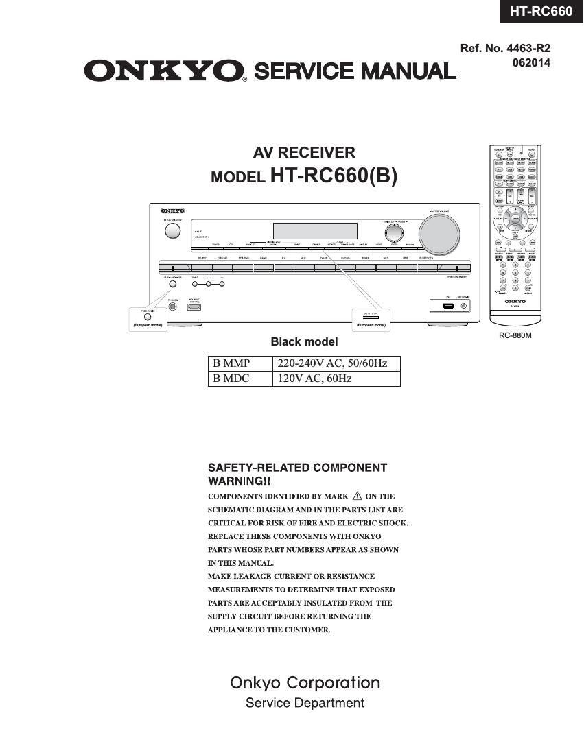
HT-RC660
Ref. No. 4463-R2
ONKYO® SERVICE MANUAL 2°
AV RECEIVER
MODEL HT-RC660(B)
{imp-an mom!)
RC»880M
Black model
B MMP 220-240V AC, 50/60Hz
B MDC 120V AC, 60Hz
SAFETY-RELATED COMPONENT
WA R N I N G ! !
COMPONENTS IDENTIFIED BY MARK A ON THE
SCHEMATIC DIAGRAM AND IN THE PARTS LIST ARE
CRITICAL FOR RISK OF FIRE AND ELECTRIC SHOCK.
REPLACE THESE COMPONENTS WITH ONKYO
PARTS WHOSE PART NUMBERS APPEAR AS SHOWN
IN THIS MANUAL.
MAKE LEAKAGE-CURRENT OR RESISTANCE
MEASUREMENTS TO DETERMINE THAT EXPOSED
PARTS ARE ACCEPTABLY INSULATED FROM THE
SUPPLY CIRCUIT BEFORE RETURNING THE
APPLIANCE TO THE CUSTOMER.
Onkyo Corporation
Service Department
Page 2
TX-NR535/636/737/838/DTR-30.6/40.6/50.6/HT-R593/693/993/HT-RC660
DEBUG MODE-1
AUDIO DEBUG MODE-1/5
The operations of DSP and DIR etc are able to checked by the information displayed on FL in this debug mode.
This information will help to analysing digital audio no sound trouble,
To set in Debug mode
1. Press twice the ON/ STANDBY key while pressing the DISPLAY key.
e-Q- 7 The version number of Microprocessor is displayed
M1'03/14307ALN only for 3 seconds
2 Press + (TONE) button while the version number of microprocessor is displayed.
e.g. N1.02/14210ALA _ ESE/\f/grrsgiosggglerZer of DSP Is displayed
3. Press DISPLAY button while the version number of DSP is displayed.
89 0A0002: :00 Step4
4. Proceed to the next step by pressing the DISPLAY key.
ANA .'o:NON:C: Step-2
4v
1:ANA 048k048k Step-3
4v
AUDIO dubug mode
2/0. 01 2. 053/4 Step-4 The status of DSP and DIR etc
4' will be displayed.
2:0:PCM :PCM Step-5
4v
00:X:F.'OFF Step-6
4v
SPO0F*00F00409 Step-7
4v
48 482568 TB Step-8 i
4v
L :0000 0000
vi
SW :0000 0000
4v
Exit
Page 13
OPERATION CHECK-2
CONFIRMATION OF MODEL NAME AND DESTINATION
Model name and destination can be confirmed the following operation.
[TV/CD] + [ON/STANDBY] 4» [DIMMER](FIT/PTYITP) 4» rrONE] *4
e.g. A:Value of AD port of BAND
N H 5 3 5 D X 2 0 0 0 B:Value of AD port oi |N|T1
f TT T T C:Value oi AD port of INsz
FL DIS Name Destination A B C D D:Value of AD port of INIT3
Model Name Destination Number Writing Data FL Display
TX-NR636 DD/DC 2000 2000 TX-NR636 Dx N R 6 3 6 D X 2 0 0 0
TX-NR636 DF 0000 0000 TX~NR636 DF N R 6 3 6 D F 0 0 0 0
TXaNR636 xx 8000 8000 TX-NR636 XX N R 6 3 6 x X 8 0 0 0
TX-NR636 JJ 4000 4000 TX-NR636 JJ N R 6 3 6 J J 4 0 0 0
HT»RCE60 DD/DC 2002 2002 HTaRC660 Dx R C 6 6 0 D X 2 0 0 2
HT»RCG60 XX 8002 8002 HT-RC660 XX R C 6 6 0 X X 8 0 0 2
DTR-30.6 DX 2040 2040 DTR»30.6 Dx D T R 3 0 6 D X 2 0 4 0
DTR-30.6 Xx 8040 8040 DTR»30.8 XX D T R 3 0 6 X X 8 0 4 0
DTR~30.6 JJ 4040 4040 DTR»30.6 JJ D T R 3 0 6 J J 8 0 4 0
TXaNR737 DD/DC 2200 2200 TXANR737 Dx N R 7 3 7 D X 2 2 0 0
TX-NR737 DF 0200 0200 TX-NR737 DF N R 7 3 7 D F 0 2 0 0
TXANR737 Xx 8200 8200 TX»NR737 XX N R 7 3 7 X X 8 2 0 0
DTR-40.6 DX 2240 2240 DTR-40.6 Dx D T R 4 0 6 D X 2 2 4 0
DTR-40.6 XX 8240 8240 DTR»40.6 XX D T R 4 0 6 X X 8 2 4 0
TXANR838 DD/DC 2400 2400 TX-NR838 Dx N R 8 3 8 D X 2 4 0 0
TX-NR838 XX 8400 8400 TX-N R838 XX N R 8 3 8 X X 8 4 0 0
TX-NR838 JJ 4400 4400 TXaNR838 JJ N R 8 3 8 J J 4 4 0 0
DTR~50.6 DX 2440 2440 DTR-50.6 Dx D T R 5 0 6 D X 2 4 4 0
DTR-50.6 XX 8440 8440 DTR»50.6 XX D T R 5 0 6 X X 8 4 4 0
HT-R993 DD/DC 2600 2600 HT»R993 Dx H T R 9 9 3 D X 2 6 0 0
HT~R993 XX 8600 8600 HT-R993 XX H T R 9 9 3 X X 8 6 0 0
TEST MODE FOR OPERATION
[Caution]Dont change setting (TONE,SETUP,etc) from initial setting before move to test mode.
Do the following operation.
1. Set the following VOL level.
VOL level
25
30
Model
TX-NR636, DTR-30.6
TX-NR737, TX-NR838, DTR-40.6, DTR-50.6
2. rrV/CD] + [ON/STANDBY]
TEST-_
3. Press the following button, while "TEST - " is displayed, then each test mode is set.
Button Test Mode Button Test Mode Button Test Mode
[BD/DVD] 1-00 [GAME] 4-00 [MEMORY] KEY TEST
[CBL/SATJ 2-00 [PG] 5-00 rl'UNlNG MODE] llllNGTlIVER/ViI-Fi ched<
[STB/DVR] 3-00 [AUX] 6-00 [DIMMER](RT/PTY/TP) FL TEST
[ENTER] FIRMWARE COMEINATIOV max
In the test mode, (TONE)- button is TEST MODE DOWN and (TONE)+ button is TEST MODE UP.
e.g. TEST 1-00 -> TEST 1-01 -> TEST 1-02 - - - - TEST 2-00
IDLING TIMER (TEST 1-01)
This mode is used for aging for idling.
Once the following test mode is set, idling timer mode works.
Idling timer mode includes the following functions.
Test mode TEST 1-01
Function Timer Refer to CONFIRMATION OF VOLTAGE-DETECTION PROTECTORS (next page).
Voltage-detection protector check Refer to CONFIRMATION OF UPDATE ROUTE (next page).
F/W update route test Refer to CONFIRMATION OF Wi-Fi CONNECTION (next page).
Wi-Fi connection check Referto CONFIRMATION OF ZONE2 DAC ROUTE (next page).
Z2 DAC route check by playing USB flash device
WAV file L+FICI1 and Rch repetition (1sec each)
Once the above test mode is set, AVR's status changes to idling timer mode and voltage-detection protector check automatically begins.
If voltage-detection protector check is all OK, Wi-Fi connection check automatically begins.
Even if one channel of voltage-detection protector check is NG, Wi-Fi connection check doesn't begin.
Page 16
TX-NR636/ 838/ HT-RC66 HT-R993/ DTR-
OPERATION CHECK-5
CONFIRMATION OF FL TUBE AND LED
1. Do the following operation.
[TV/CD] + [ON/STANDBY] a [DIMMER]
2. Confirm that all LEDs and all segments of FL tube are lit.
CONFIRMATION OF HEAD PHONE OPERATION
Confirm the headphone indicator when headphones plug is inserted into the PHONES jack.
CONFIRMATION OF FM RADIO OPERATION
1. Setting of Signal Generator(SG)
Carrier frequency any
Modulation 1 kHz
Deviation 75kHz
Output level 35dBu
2. Waveform confirmation
Set the signal of SG as following channels and confirm output is the following table.
Outout
SG Input Lch R ch
(1) R ch only No Yes
(2) L + R ch Yes Yes
3. Confirmation of Stereo indicator
Set SG as stereo and confirm stereo indicator is on.
4. Confirmation of Auto stop operation
Do auto tuning (Press TUNING UP or TUNING DOWN button) and confirm that the searching stops when a station that
is set by SG is found.
CONFIRMATION OF RDS (RADIO DATA SYSTEM) OPERATION (Applied to MPP/MPB/MM* type)
1. lnput 98MH2,30dBp signal modulated with RDS data.
2. When a PS information is received, the name of the station "FlDS TEST" shall be displayed within 2 seconds
instead of the frequency.
CONFIRMATION OF OSD(ON SCREEN DISPLAY) OPERATION
1. When DISPLAY button is pushed, confirm that OSD is displayed in HDMI SUB/ZONE2 Out.
2. Confirm that specified operations for ENTER(with 4-cursor) buttons are made.
IApplied model ITX-NR737/B38,DTR-40.6/50.6 |
CONFIRMATION OF CEC OPERATION
1. Connect AVRs HDMI OUT to HDMI input of appliance compatible with CEC(S|NK or REPEATER) by HDMI cable.
2. Turn on the power to the AVFl
3. Do the following operation.
3-1. set the volume level to 25(TX-NR636, DTR-30.6) or 30(TX-NFl737, 838, DTR-40, 50.5).
3-2. [TV/CD] + [ON/STANDBY] 4» [AUX]
to the following test mode.
TEST 6-00
FL tube will display "OK" or "NG".
CONFIRMATION OF DOLBY TEST TONE
1. Press TEST TONE on remote controller then press CH SELECT repeatedly.
Set turn to Dolby Test mode tone Check speaker condition.
2. Please check that a sound comes out from each channel.
-> FL ch -> C ch -> FR ch -> SR ch -> SBR ch -> SBL ch -> SL ch -> SW ch ->
Page 23
TX-NR636/ 737/ 838/ HT-RC660/ HT-R993/ DTR-30 I40
FIRMWARE UPDATE-1/2
USB Update (service mode)
CONFIDENTIALITY NOTICE:
The contents of the Firmware Update is Confidential Information as defined in the applicable Service Center Agreement.
It is for the exclusive use ofOnkyo/Integra Authorized Independent Service Centers.
Dissemination or posting of this Firmware Update to any non-authorized individual or company is strictly prohibited.
Failure to keep this information confidential may result in the loss of service center authorization.
[Version Check]
Refer to OPERATION CHECK-l about the way ofshowing firmware version.
[Preparation]
1. Connect the USB storage device to your PC. Ifthere is any data in the USB storage device) remove it.
2. Download the firmware file (package file) from the Onkyo FTP-server.
However European service partners should download the firmware file (package file) from the ExtraNet.
Onkyo FTP-server: ftp://manex.onkyo.co.jp/iservicefwa/TX-NR636
ID and Password are those we informed when changed.
Filename is as follows: ONKAVROO187****************.zip
Unzip the downloaded file. A following file is created.
ONKAVROOIS ************_0fl
ONKAVROO18T************_0t2
ONKAVROOI87************_0f3
ONKAVROO187************_0f4
ONKAVROO187************_0f5
3. Copy it to the USB storage device. Be careful not to copy the zip file.
4. Remove the USB storage device from your PC.
Page 93
44/59 PAGE
3C3921 CHIP TYPE CERAMIC CAPACITOR CK725BoJr22eM 1 332092267R2
308922 CHIP TYPE CERAMIC CAPACITOR CK725BOJ7226M 1 332092267R2
3C0931 CHIP TYPE CERAMIC CAPACITOR CK72581H7103K0 1 332031035R1
3C3932 CHIP TYPE CERAMIC CAPACITOR CK725B1CV104K0 1 332011045R1
3C3933 CHIP TYPE CERAMIC CAPACITOR CK72581E7106K 1 332221065R2
308934 CHIP TYPE CERAMIC CAPACITOR CK72sB1 E7106K 1 332221065R2
3C0935 CHIP TYPE CERAMIC CAPACITOR CK72581H7103K0 1 332031035R1
308936 CHIP TYPE CERAMIC CAPACITOR CK725BOJ7226M 1 332092267R2
3C3937 CHIP TYPE CERAMIC CAPACITOR CK725BoJr22eM 1 332092267R2
308939 CHIP TYPE CERAMIC CAPACITOR CK725BOJ7226M 1 332092267R2
3C0941 CHIP TYPE CERAMIC CAPACITOR CK72581H7103K0 1 332031035R1
3C3942 CHIP TYPE CERAMIC CAPACITOR CK725B1CV104K0 1 332011045R1
3C3943 CHIP TYPE CERAMIC CAPACITOR CK72581E7106K 1 332221065R2
308944 CHIP TYPE CERAMIC CAPACITOR CK72sB1 E7106K 1 332221065R2
308945 CHIP TYPE CERAMIC CAPACITOR CK72581H7103K0 1 332031035R1
308946 CHIP TYPE CERAMIC CAPACITOR CK725BOJ7226M 1 332092267R2
3C3947 CHIP TYPE CERAMIC CAPACITOR CK725BoJr22eM 1 332092267R2
308951 CHIP TYPE CERAMIC CAPACITOR CK72sB1 H7103K0 1 332031035R1
3C0952 CHIP TYPE CERAMIC CAPACITOR CK72581 C71 (mm 1 332011045R1
308953 CHIP TYPE CERAMIC CAPACITOR CK725B1E7106K 1 332221065R2
308954 CHIP TYPE CERAMIC CAPACITOR CK72581E7106K 1 332221065R2
308955 CHIP TYPE CERAMIC CAPACITOR CK72sB1 H7103K0 1 332031035R1
icsese CHIP TYPE CERAMIC CAPACITOR CK72580J7226M 1 332092267R2
308957 CHIP TYPE CERAMIC CAPACITOR CK725BOJ7226M 1 332092267R2
3C3901 CHIP TYPE CERAMIC CAPACITOR CK72581H7103K0 1 332031035R1
308962 CHIP TYPE CERAMIC CAPACITOR CK72sB1 C1 04K0 1 332011045R1
icsses CHIP TYPE CERAMIC CAPACITOR CK72581 E7106K 1 332221065R2
308964 CHIP TYPE CERAMIC CAPACITOR CK725B1E7106K 1 332221065R2
iCBses CHIP TYPE CERAMIC CAPACITOR CK72581H7103K0 1 332031035R1
308966 CHIP TYPE CERAMIC CAPACITOR CK725BOJ7226M 1 332092267R2
3C0957 CHIP TYPE CERAMIC CAPACITOR CK72580J7226M 1 332092267R2
303971 CHIP TYPE CERAMIC CAPACITOR CK732816V7106K 1 332071065R2
3C3975 CHIP TYPE CERAMIC CAPACITOR CK72581E7106K 1 332221065R2
308976 CHIP TYPE CERAMIC CAPACITOR CK725BOJ7226M 1 332092267R2
3C0930 CHIP TYPE CERAMIC CAPACITOR CK72581A7105K0 1 332001055R1
303931 CHIP TYPE CERAMIC CAPACITOR CK732816V7106K 1 332071065R2
308982 CHIP TYPE CERAMIC CAPACITOR CK72581A7105K0 1 332001055R1
308983 CHIP TYPE CERAMIC CAPACITOR CK732816V7106K 1 332071065R2
3C0934 CHIP TYPE CERAMIC CAPACITOR CK72581A7105K0 1 332001055R1
303985 CHIP TYPE CERAMIC CAPACITOR CK732816V7106K 1 332071065R2
EIRESISTOR]
3R1002 CHIP TYPE CARBON RESISTOR RN72K1J7151JE 1 435031514R1
3R1003 CHIP TYPE CARBON RESISTOR RN72K1J7151JE 1 435031514R1
3R10o4 CHIP TYPE CARBON RESISTOR RN72K1J7151JE 1 435031514R1
3R1005 CHIP TYPE CARBON RESISTOR RN72K1I331JE 1 435033314R1
3R10oe CHIP TYPE CARBON RESISTOR RN72K1J7560JE 1 435035604R1
3R10o7 CHIP TYPE CARBON RESISTOR RN72K1J7105JE 1 435031054R1
3R10oa CHIP TYPE CARBON RESISTOR RN72K1J7102JE 1 435031024R1
3R101o CHIP TYPE CARBON RESISTOR RN72K1J7103JE 1 435031034R1
3R1011 CHIP TYPE CARBON RESISTOR RN72K1I220JE 1 435032204R1
3R1012 CHIP TYPE CARBON RESISTOR RN72K1J7220JE 1 435032204R1
3R1013 CHIP TYPE CARBON RESISTOR RN72K1J7220JE 1 435032204R1
3R1014 CHIP TYPE CARBON RESISTOR RN72K1I220JE 1 435032204R1
3R1015 CHIP TYPE CARBON RESISTOR RN72K1I220JE 1 435032204R1
3R101e CHIP TYPE CARBON RESISTOR RN72K1J7220JE 1 435032204R1
3R1017 CHIP TYPE CARBON RESISTOR RN72K1J747OJE 1 435034704R1
3R1019 CHIP TYPE CARBON RESISTOR RN72K1J7470JE 1 435034704R1
3R1020 CHIP TYPE CARBON RESISTOR RN72K1J7391JE 1 435033914R1
3R1021 CHIP TYPE CARBON RESISTOR RN72K1J7101JE 1 435031014R1
3R1022 CHIP TYPE CARBON RESISTOR RN72K1J7151JE 1 435031514R1
3R1023 CHIP TYPE CARBON RESISTOR RN72K1I221JE 1 435032214R1
3R1024 CHIP TYPE CARBON RESISTOR RN72K1I470JE 1 435034704R1
3R1025 CHIP TYPE CARBON RESISTOR RN72K1J747OJE 1 435034704R1
3R1026 CHIP TYPE CARBON RESISTOR RN72K1J7331JE 1 435033314R1
§R1027 CHIP RESISTOR NETWORK YCN10472217JK 1 43464022104R1
§R1027 or CHIP RESISTOR NETWORK MNR04MRAPJ221 I 1 ) 43464722104R2 N
3R1027 or CHIP RESISTOR NETWORK RM7LJ221XO4 I 1) 43484722104R2