Onkyo TXNR 515 Service Manual

This is the 130 pages manual for Onkyo TXNR 515 Service Manual.
Read or download the pdf for free. If you want to contribute, please upload pdfs to audioservicemanuals.wetransfer.com.

Page: 1 / 130
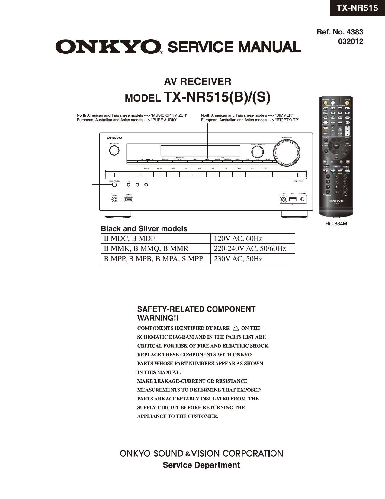
Onkyo TXNR 515 Service Manual

Extracted text from Onkyo TXNR 515 Service Manual (Ocr-read)


Page 1

TX-NR515

Ref. NO. 4383

ONKYO® SERVICE MANUAL 2°

North American and Taiwanese models -»-> "MUSIC OPTIMIZER" North American and Taiwanese models ---> DIMMEFl
European. Australian and Asian models ---> PURE AUDIO" European. Australian and Asian models ---> FlT/ PTY/ TP"

AV RECEIVER
MODEL TX-NR515(B)/(S)

Oman;

5 H : , Z ©

- RC-834M
Black and Silver models
B MDC, B MDF 120V AC, 60Hz
B MMK, B MMQ, B MMR 220-240V AC, 50/60Hz

B MPP, B MPB, B MPA, S MPP 230V AC, SOHZ

SAFETY-RELATED COMPONENT
WA R N l N G l !

COMPONENTS IDENTIFIED BY MARK A ON THE
SCHEMATIC DIAGRAM AND IN THE PARTS LIST ARE
CRITICAL FOR RISK OF FIRE AND ELECTRIC SHOCK.
REPLACE THESE COMPONENTS WITH ONKYO
PARTS WHOSE PART NUMBERS APPEAR AS SHOWN
IN THIS MANUAL.

MAKE LEAKAGE-CURRENT OR RESISTANCE
MEASUREMENTS TO DETERMINE THAT EXPOSED
PARTS ARE ACCEPTABLY INSULATED FROM THE
SUPPLY CIRCUIT BEFORE RETURNING THE
APPLIANCE TO THE CUSTOMER.

ONKYO SOUND &V|SION CORPORATION
Service Department

Page 2

SERVICE PROCEDURE-1

1. Replacing the fuses

EE This symbol located near the fuse indicates that the
fuse used is slow operating type, For continued protection against
fire hazard, replace with same type fuse, For fuse rating, refer to

the marking adjacent to the symbol.

EE Ce symbole indique que le fusible utilise est e lent.

Pour une protection permanente, n'utiliser que des fusibles de meme
type. Ce demier est indique la qu le present symbol est apposre.

NR5

REF NO. PART NAME DESCRIPTION PART NO. REMARKS
F6401 FUSE 10A-UL/T-233 252330GR l
F6401 or FUSE 10A-T/UL»ST2 252333GR !
F6402 FUSE lOA-UL/T-233 25233OGR !
F6402 or FUSE lOA-T/UL»ST2 25233SGR !
F9002 FUSE 8A-UL/T-233 252329GR !
F9002 or FUSE 8A-T/UL-ST2 252261GR !
F9002 FUSE 4A-SE-EAK 252077GR l
F9002 or FUSE 4A-SE-TLZSOV 252277GR !
F201 FUSE 4A-SEUL-TL250V 252392T !
F9001 FUSE lA-SEUL-TLZSOV 252397T !

: 120V,Canadian model

: 230V,CE(European) country model
: 230V,Austral.ian model

: 230V,UK model

2. Safety check out
(U.S,A. model only)
After correcting the original service problem, perform the following safety check before releasing the unit to the customer.
Leakage current Check
Measure the leakage current to a known earth ground (water pipe or conduct etc.) by connecting a leakage current
tester between the earth ground and exposed metal parts of the unit (inpquutput ground terminals, screw heads or metal overlays etc).
Plug the power supply cord directly into a 120Vac 60Hz wall socket and turn ON/STANDBY button on.

Any current measured must not exceed 0.5mA.

3. To initialize the unit
1. Press ON/STANDBY button while pressing down CBL/SAT button when the unit is POWER ON, then the FL displays
"CLEAR", and turn to STAND-BY,
Preset memory and each mode stored in the memory, are initialized and will return to the factory settings.

Clear

2, Remove power cord from wall outlet.

ON/STANDBY

mam

CBL/SAT

: 220/230-240V, Korean model
: 220/230-240V,Hong kong model
: 220/230-240V,Chinese model
: 120V,Taiwanese model

a Stand-by

Page 18

/ HT-RC460/470/ HT- / DTR-20.4/30.4

OPERATION CHECK-2
1.0PERATION CHECK(2/2)

1-9. CONFIRMATION OF OSD(ON SCREEN DISPLAY) OPERATION
a. When SETUP button is pushed, confirm that setup menu is displayed in HDMI Out.
b. Confirm that specified operations for ENTER(with 4-cursor) buttons are made.

1-10. CONFIRMATION OF HDMI AUDIO OPERATION.
CONFIRMATION OF HDMI IZS SIGNAL
See OPERATION CHECK-37-6 for TEST MODE operation.
a. Input the one of these signals below from HDMIl terminal.
DTS-HD MasterAudio 7.1ch
Dolby TrueHD 7.1ch
LPCM 7.1ch
b. Change the state to TEST 6-00. Confirm the signal is output from L/R,SW/C,SL/SR,SBL/SBR.
c. When TEST 6-08, confirm the sound(HDMIl input) outputs from the TV.
CONFIRMATION OF HDMI SPDIF SIGNAL
d. SPDIF signal is input from HDMI terminal.
e. When TEST 6-06, confirm the sound(HDMI INl)outputs from the speaker.
f. When TEST 6-07, confirm the sound(BD/DVD analog input) outputs from the TV.(VIDEO is HDMIl)
CONFIRMATION OF HDMI DSD SIGNAL.
g. When TEST 6-10 confirm the sound ofDSD 5. lch input HDMI IN 3, output from the speaker.

1-11. VIDEO FUNCTION CHECK
See OPERATION CHECK-37-6 for TEST MODE operation.
a. Confirm Video output signal as shown Table 2, while Video signal are input as shown Table 1.
NOTE 1: Confirm the HDMI path at 1080p signal.
NOTE 2: Confirm the TESTS-08(COMPONENT--->HDMI) path at 480i signal.

Table 1 Table 2
Inpul Composite Vldco Component HDMI Compnsltc Video Componcnt HDMI
BD/DVD A m1 y mi H Monitor our our Mam Sub
CBL SAT E INZ ('1 INZ 1 Test nmdc
STE DVR c w in} K swap/DVD) A H H
GAME D \m 1N4 L 5701(CBL SAT) B (. J J
PC No INS M sroztsna DVR) C K K
[N6 N0 1N6 N SrmttiAME) D L L
m7 No 1N7 0 54mm) M V1
AUX E No AUX P 5705(AL'X ms) N 1
USE E No srontwn m7. 0 0
54mm AUX) P l7
sroxmornvn) A F F F
srogtusa Aux) E E E

b. OPERATIONS OF VIDEO SIGNAL-DETECTION
Set the TEST MODE to "TEST 5-00".
When the component video signal is input to INl, confirm that "RDS" ofFL TUBE lights.

1-12. CONFIRMATION OF 12V TRIGGER OPERATIONS.(DTR-20.4/30.4 ONLY)
a. After checking that there is no output from 12V TRIGGER A terminaLit checks that
there is an output of 12Vi10%/150mA after switched the "TESTZ-l l".
b. After checking that there is no output from 12V TRIGGER B terminal,it checks that
there is an output of lZVilOVo/ZSmA after about 1 seconds switched the "TESTZ-lZ.
c. After checking that there is no output from 12V TRIGGER C terminal,it checks that
there is an output of lZVilOVn/ZSmA after 2 seconds switched the "TEST2-13.

1-13. CONFIRMATION OF COOLING FAN OPERATION (TX-NR616/HT-RC470/DTR-30.4 only)
See OPERATION CHECK-3,6 for TEST MODE operation.
a. Confirm to fan no rotate
b. When TEST 4-36 or TEST 4-37, confirm to fan rotate.

1-14. MISCELLANEOUS
a. Please confirm LED and FL displaying by the FL test mode.
And confirm the destination setting. ---> See to OPERATION CHECK-3
b. Confirm the version ofeach firmware.---> See to SERVICE PROCEDURE-2
c. Confirm the Firmware Combination Check.---> See to OPERATION CHECK-3
d. Please confirm the Check Sum.---> See to OPERATION CHECK-3"

Page 47


Farts marked by "NSF" are generally unavailable because
they are not in our Master Spare Pans Lisl.

NOTE : THE COMPONENTS IDENTIFIED BY THE MARK
I ARE CRITICAL FOR RISK OF FIRE AND
ELECTRIC SHOCK. REPLACE ONLY WITH PART
NUMBER SPECIFIED.

(B) : Black model
(5) : Silver model

:
:

:

EEXPLODED VIEW PARTS LIST

120V,Canadian model
230V,CE(European) country model

: 230V,Auslralian model
:230V,UK model
:

220/230-240V, Korean model

: 220/230-240V,Hong kong model
:

220/230-240V,Chinese model
120V,Taiwanese model

1/83 PAGE

REF. No. PART NAME DESCRIPTION Q'TY PART No. (SN) REMARKS
{$V. ' Q 1 ,.

06050 TR 25C519870 1 2203063

060500; TR 25014680 11) 2202523

060500; TR 250146871) (1) 2202526

060500; TR 25c5198eR (1) 2203062

QGOSOA ISOSHEET AC238 2 223024
QGOSOB ISOSHEET ISOSHEET 6 223050
Q6051 TR 25C519870 1 2203063

060510; TR 25014680 11) 2202523

060510; TR 250146871) (1) 2202526

060510; TR 25c5198eR (1) 2203062

06052 TR 25C519870 1 2203063

060520; TR 250146870 (1) 2202523

060520; TR 250146871) (1) 2202526

060520; TR ZSCSIQBVR 11) 2203062

06053 TR ZSC519870 1 2203063

060530; TR 250146870 (1) 2202523

060530; TR 250146871) 11) 2202526

060530; TR 25c5198eR (1) 2203062

06054 TR 25C519870 1 2203063

060540; TR 25014680 11) 2202523

060540; TR 250146871) (1) 2202526

060540; TR 25c5198eR (1) 2203062

06055 TR 25C519870 1 2203063

060550; TR 250146870 (1) 2202523

060550; TR 250146871) (1) 2202526

060550; TR ZSCSIQBVR 11) 2203062