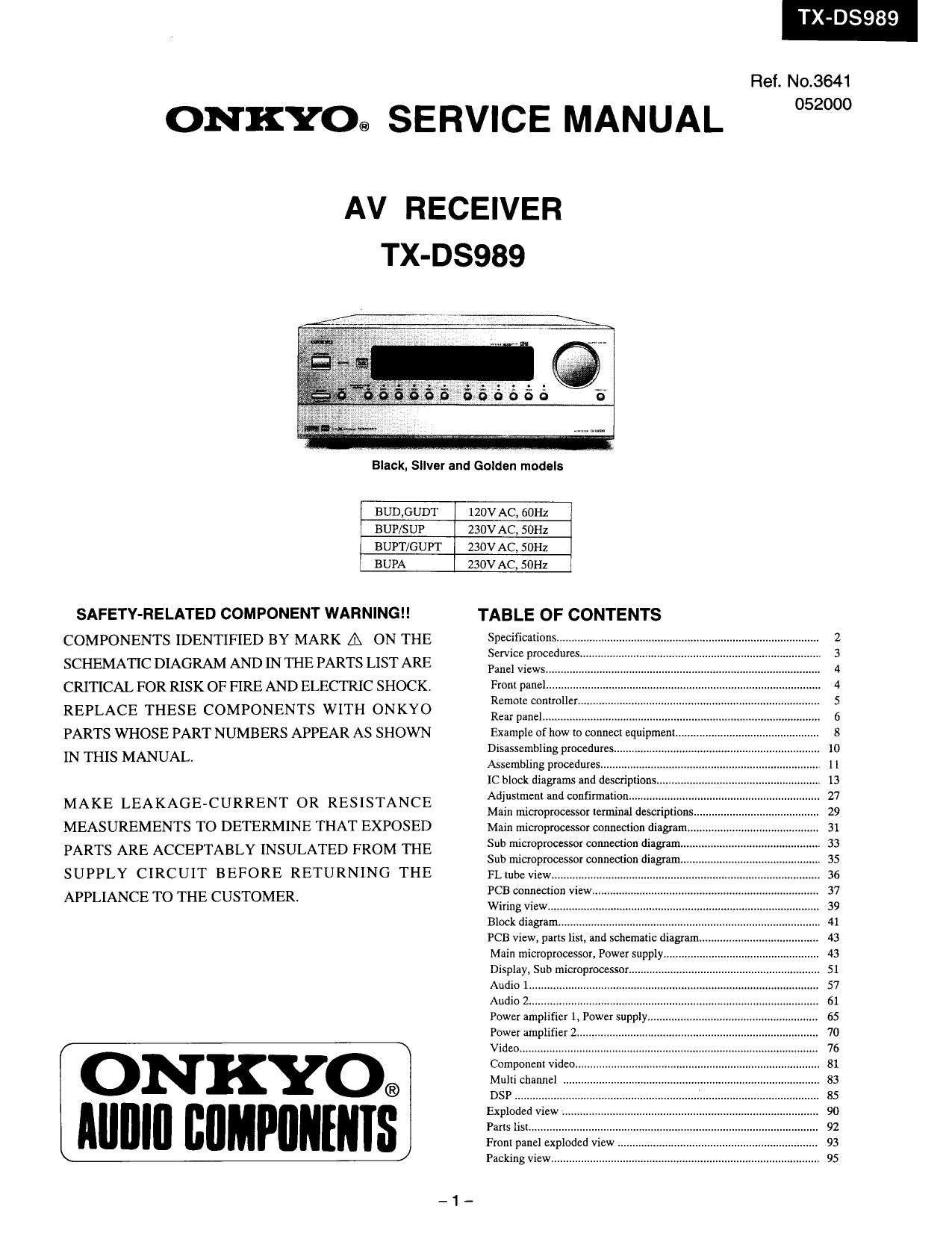
Onkyo TXDS 989 Service Manual
This is the 44 pages manual for Onkyo TXDS 989 Service Manual.
Read or download the pdf for free. If you want to contribute, please upload pdfs to audioservicemanuals.wetransfer.com.
Extracted text from Onkyo TXDS 989 Service Manual (Ocr-read)
Page 1
ONKYO® SERVICE MANUAL
T 03989
Ref. No.3641
052000
AV RECEIVER
TX-D5989
Black. Silver and Golden models
BUD,GUDT
120V AC, 601-12
BUP/SUP
230V AC, SOHZ
BUPT/GUPT
230V AC, SOI-Iz
BUPA
230V AC, SOHZ
SAFETY-RELATED COMPONENT WARNING
COMPONENTS IDENTIFIED BY MARK A ON THE
SCHEMATIC DIAGRAM AND IN THE PARTS LIST ARE
CRITICAL FOR RISK OF FIRE AND ELECTRIC SHOCK
REPLACE THESE COMPONENTS WITH ONKYO
PARTS WHOSE PART NUMBERS APPEAR AS SHOWN
IN THIS MANUAL.
MAKE LEAKAGE-CURRENT OR RESISTANCE
MEASUREMENTS TO DETERMINE THAT EXPOSED
PARTS ARE ACCEPTABLY INSULATED FROM THE
SUPPLY CIRCUIT BEFORE RETURNING THE
APPLIANCE TO THE CUSTOMER
ONKYO®
IIIIIIII BIIMPIIIIIIIIS
TABLE OF CONTENTS
Specifications... 2
Service procedu 3
Panel views 4
From panel 4
Remote controller 5
Rear panel,....,i. 6
Example of how to connect equipmcn 8
Disassembling procedures" 10
Assembling procedures. 1 1
1C block diagrams and descriptions. 13
Adjustment and confirmation ...... 27
Main microprocessor terminal descriptions" 29
Main microprocessor connection diagram
Sub microprocessor connection diagram.
Sub microprocessor connection diagram
FL tube view..,.,.«.
PCB connection View
Wiring View.
Block diagram.
PCB View, parts list, and schematic diagram
Main microprocessor, Power Suppl
Display, Sub microprocessor.
Audio
Audio
Power amp I icr , ower supp
Power amplifier 2.
Video ...............
Component video.
Multi channel .
DSP
Explode View .
Paris list.....,..
Front panel exploded view
Packing View......,,.,,..,.4..
Page 6
X-D8989
4.Attachment of shaft assembly
Apply Floil on the groove of holders. Attach the gear 8 as shown below.
G roove
Gear A
Groove Holder L
Holder R
Hang the spring from the down side of lever.
Attach the gear A to the holder Fl, and insert
the shaft A to fix the gear A.
Holder L
Spring
down side
Spring ) >
Lever 1.lnsert the retainer 8.
LeverL V L ' T h A l k f It
- 2. urn t e gear c 00 wise u y.
down Side Sh ftA .
a Gear A 3.|nsert the headphone jack to the
hole of front panel.
Insert the shaft to the shaft L and the shaft R. 4.Attach the motor assembly.
Q/jens 6B(BC) 5.Attach the part above on the
Apply floilwe-V l - +
fiRétainerW front panel.
Gears
Shaft R
Shaft
Shaft L
Turn Gear A counter .
clockwise fully. PC board
Plastic rivet '
Turn the gear clockwise fully and
insert the PC board A.
Fix the PC board by the plastic rivet.
Cross
-12-