Onkyo TXDS 797 Service Manual 2

This is the 7 pages manual for Onkyo TXDS 797 Service Manual 2.
Read or download the pdf for free. If you want to contribute, please upload pdfs to audioservicemanuals.wetransfer.com.

Page: 1 / 7
Onkyo TXDS 797 Service Manual 2

Extracted text from Onkyo TXDS 797 Service Manual 2 (Ocr-read)


Page 1

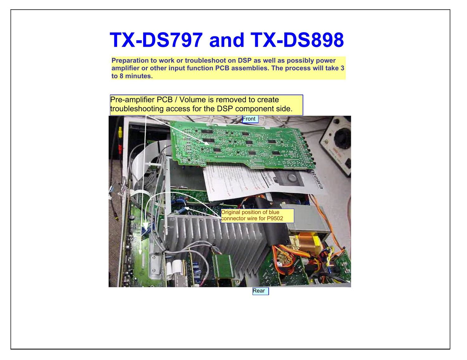
TX-DS797 and TX-DS898 D S P Disconnect P9502 connector wire (Blue) and then remove all 8 screws holding heat sink to the bottom chassis. Remove white ribbon connector from P7701A DSP side. Disconnect all speaker connectors from P6810, P6812, P6008A and P6008B. Remove secondary power connector from P6951 location found on power relay PCB assembly. Set power amplifier on it side as seen above. When attempting to repair or trouble shoot DSP, Video PCB and all input PCBs, follow disassembly given below.

Page 2

TX-DS797 and TX-DS898 Secondary power connector from P6951 being disconnected. JL6953B and P6952A found to the right may be disconnected. With the power amplifier set on its side, the input PCB assemblies are exposed for easy troubleshooting and repair. Individual PCB may be checked without the other. S-video may not work without the composite, but if the composite works the problem with S-video is simple to asses. Speaker relay is fully functional even though there is no audio passing through as main amp is disabled. For additional ease Tuner module and its support PCB may be removed.