Onkyo TXDS 575 X Schematic 2

This is the 6 pages manual for Onkyo TXDS 575 X Schematic 2.
Read or download the pdf for free. If you want to contribute, please upload pdfs to audioservicemanuals.wetransfer.com.

Page: 1 / 6
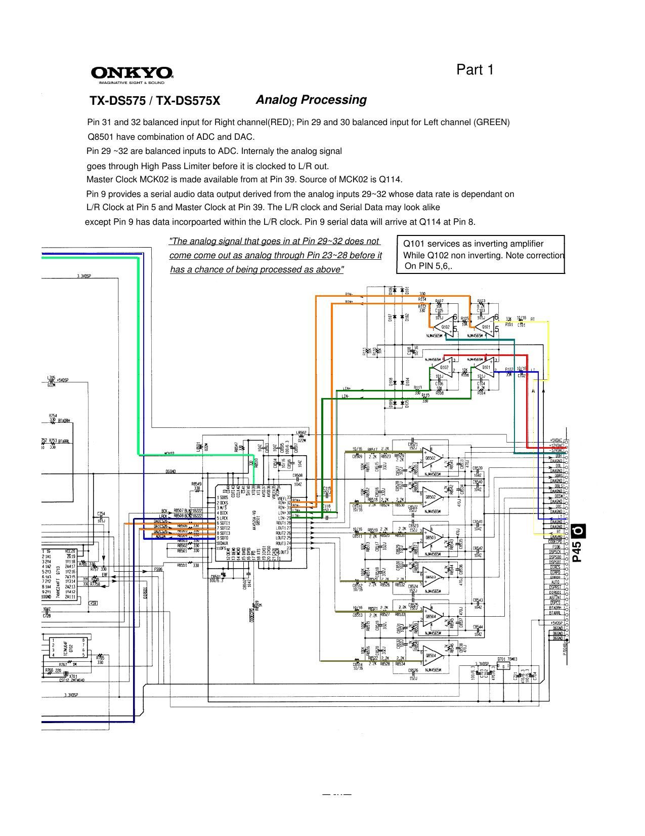
Onkyo TXDS 575 X Schematic 2

Extracted text from Onkyo TXDS 575 X Schematic 2 (Ocr-read)


Page 1

Analog Processing TX DS575 / TX DS575X Analog Processing Part 2 fQ fQ TX -DS575 / TX -DS575X Part 2 Audio Data from Q8501 Pin 9 arrives at Pin 8 o f Q114. Same data will find its way out at pin 20 of Q114. It is important X0 XI Pin 5 and Pin 6 work correct and that 12 2MhzIt is important X0 -XI Pin 5,and Pin 6 work correct and that 12.2Mhz oscilation is present No noticable drift or Jitter should be noticedoscilation is present . No noticable drift or Jitter should be noticed .

Page 2

ANALOG PROCESSING Part 3 Q114 Pin 15 =L Analog Digital =H TX-DS575 / TX-DS575X Q114 Pin 15 L Q114 Pin 17 = H H =L It is conditional that audio data is present at Pin 8 (DAUX) of Q114 and that X-tal X103 is ON in-order for Q114 to operate properly The digital condition set forth at Pin 15 and 17 along a precence of digita datato operate properly . The digital condition set forth at Pin 15 and 17 along a precence of digita data at Pin 13, 12 and 11 will turn OFF X103. 4.6vdc Q114 waveforms when input is analog. Q114 Pin 27 when digital selected and digital signal detected.digital signal detected. MCK01,MCK02 at Q114 Pin 24 & 23 MCK01, MCK02 after L171 &L170 Pin 19 LRCK Pin 26 digital source selected. Absent when analo g. LRCK g