Onkyo TX 840 M Service Manual

This is the 23 pages manual for Onkyo TX 840 M Service Manual.
Read or download the pdf for free. If you want to contribute, please upload pdfs to audioservicemanuals.wetransfer.com.

Page: 1 / 23
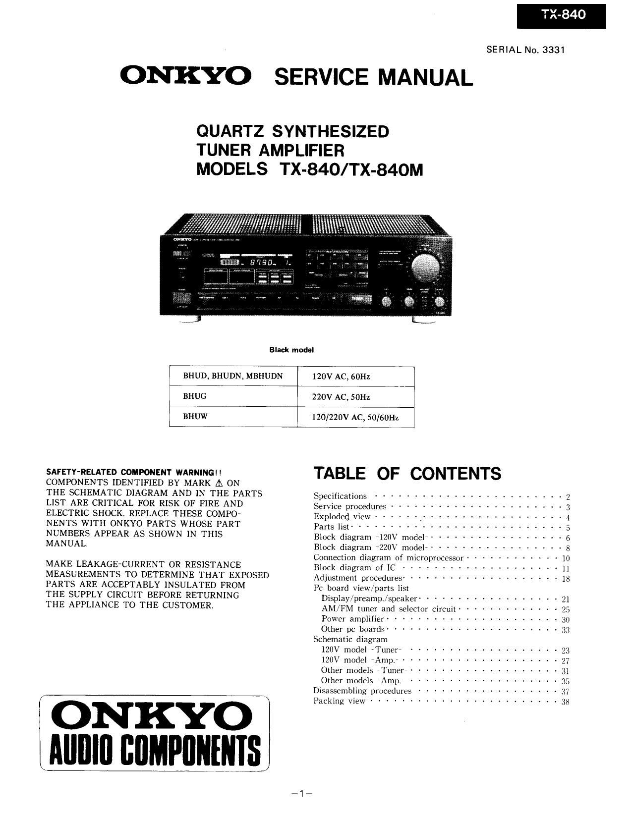
Onkyo TX 840 M Service Manual

Extracted text from Onkyo TX 840 M Service Manual (Ocr-read)


Page 1

SERIAL No. 3331

ONKYO SERVICE MANUAL

QUARTZ SYNTHESIZED
TUNER AMPLIFIER
MODELS TX-840/TX-84OM

Black model
BHUD, BHUDN, MBHUDN 120V AC, 60H:
_I
BHUG 220V AC, SOHz
BHUW 120/220V AC, SO/60Hz

SAFETY-RELATED COMPONENT WARNING! !
COMPONENTS IDENTIFIED BY MARK A ON
THE SCHEMATIC DIAGRAM AND IN THE PARTS
LIST ARE CRITICAL FOR RISK OF FIRE AND
ELECTRIC SHOCK. REPLACE THESE COMPO
NENTS WITH ONKYO PARTS WHOSE PART
NUMBERS APPEAR AS SHOWN IN THIS
MANUAL.

MAKE LEAKAGECURRENT 0R RESISTANCE
MEASUREMENTS TO DETERMINE THAT EXPOSED
PARTS ARE ACCEPTABLY INSULATED FROM
THE SUPPLY CIRCUIT BEFORE RETURNING

THE APPLIANCE TO THE CUSTOMER.

ONKYO
AIIIIIII IIIIMPIIIIEIIIS

TABLE OF CONTENTS

Specifications ........................ 2
Service procedures --------------------- 3
Exploded View ~~~~~~ , .................. 4
Parts list ........................... 5
Block diagram 7120\7 model ----------------- 6
Block diagram ~220V model ----------------- 8
Connection diagram of microprocessor ---------- 10
Block diagram of IC ------------------- 11
Adjustment procedures ------------------- 18
Pc board view/parts list
Display/preamp./speaker ~~~~~~~~~~~~~~~~~~ 21
AM/FM tuner and selector circuit ------------ 25
Power amplifier -------------------- 30
Other pc buards --------------------- 3;;
Schematic diagram
120V model 'Tunerr ------------------- 23
120V model 'Amp. ................ 27
Other models Tuner ------------------ 3]
Other models rAmpi ................... 35
Disassembling procedures ------------------ 37
Packing View ........................ 3x

Page 12

Pin No. Terminal Descriplian

52 Sa

53 Sb

54 Sc

55 Sd These are the output terminal for segment signal.

56 Se "H" when active,

57 Sf

58 Sg

59 Sh

60 Si

61 Si

62 Sk

63 S]

64 VDD This is the divice power source terminalAt the time of operationxhe supply is 5V.The internal

data memory(RAM) is maintained by means of the super capacitor.
FM50K (FM band setting)
FMSOK Region Frequency range Channel space Reference frequency IF frequency

1 Bumper 87.50 ~108.00MH2 SOkHz ZSkHz 107MHz
(l U.SiA. 87.9 ~107.9MH2 200kHz ZSkHz 10.7MHz

,12_

Page 22

DISASSEMBLING PROCEDURES

1. Top cover
Remove a screw (3TTS+8BQ(BC)) holding the top cover and the back panel.
Remove the four screws (3TTS+SB(BC)) holding the back panel and the chassis.

2. Front panel
Remove the top cover.
Remove the six screws (3TTP+8P(BC)) holding the front panel and the front backet.

3. Power amplifier pc board
Remove the top cover.
Remove the five screws A.
Cut the binder B.

4. FM/AM tuner and selector switch pc board

Remove the top coverl

Remove the three screws C holding the pe board and chassis.
Remove the five screws D holding the back panel and chassis.
Remove the pc board from the two holders.

_37_