Onkyo TX 830 Service Manual

This is the 30 pages manual for Onkyo TX 830 Service Manual.
Read or download the pdf for free. If you want to contribute, please upload pdfs to audioservicemanuals.wetransfer.com.

Page: 1 / 30
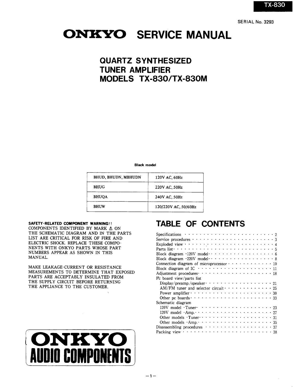
Onkyo TX 830 Service Manual

Extracted text from Onkyo TX 830 Service Manual (Ocr-read)


Page 1

T 830

SERIAL No. 3293

ONKYO SERVICE MANUAL

QUARTZ SYNTHESIZED
TUNER AMPLIFIER
MODELS TX-830/TX-830M

Black model

BHUD, BHUDN, MBHUDN 120v Ac, 60Hz

BHUG 220v Ac, 501-12

BHUQA 240v Ac, SOHz

BHUW 120/220v AC, 50/60Hz
SAFETY-RELATED COMPONENT WARNING TABLE OF CONTENTS
COMPONENTS IDENTIFIED BY MARK A ON
THE SCHEMATIC DIAGRAM AND IN THE PARTS specifications ........................ 2
LIST ARE CRITICAL FOR RISK OF FIRE AND Service procedures ...................... 3
ELECTRIC SHOCK. REPLACE THESE COMPO- Exploded view ...... . .................. 4
NENIS WITH ONKYO PARTS WHOSE PART pans list ........................... 5
NUMBERS APPEAR AS SHOWN IN THIS Block diagram .gov model .................. 6
MANUAL Block diagram -220v model ------------------ a

Connection diagram of microprocessor ------
Block diagram of 1C ------------- .
Adjustment procedures -------------------- 18
PC board view/parts list

MAKE LEAKAGECURRENT OR RESISTANCE
MEASUREMENTS TO DETERMINE THAT EXPOSED
PARTS ARE ACCEPTABLY INSULATED FROM

THE SUPPLY CIRCUIT BEFORE RETURNING

Display/preamp./speaker ----------- . 21
THE APPLIANCE TO THE CUSTOMER AM/FM tuner and selector circuit ------ . 25
Power amplifier ............... . . 30
Other pc boards --------------------- 33
Schematic diagram
120V model *Tuner- ................... 23
120V model -Amp. --------------- . 27
Other models -Tuner ------------------- 31
Other models -Amp. -------------------- 35
Disassembling procedures ------------ . 37

I ONKYO ........................ 38
Alllllll llllMPllllllllS

Page 3

REMOTE CONTROL TRANSMITTER RC-llSS/RC-HSS
Transmitter: Infrared

Signal range: Approx. 5meters(16ft.4")

Power supply: TWO "AA" batteries (1.5V X2)

Dimensions 2-1/2 " xii/4 " X 7"
Weight: lAOgrams 5.0oz.(including batteries)

Specifications and features are subject to change without notice.

SERVICE PROCEDURES

1. Replacing the fuses
For continued protection against fire hazard, replace only
with same type and same rating fuse.

D (120v) model

Circuit no. Part no. Description

F901 252050 SA (ST-6), Primary

G (220V) and Q (240V) models

Circuit no. Part no. Description

F902 252075 2.5A-SE-EAK, Primary

F903 252075 2.5A-SE-EAK, AC outlet
(Only 220V model)

F906 252070 IASE-EAK, Secondary

W (Worldwide) model

Circuit no. Part no. Description

F901 252050 5A (ST-6), Primary

F902 252075 2.5A-SE-EAK, Primary

2. Change of FM/AM band step.
With the exception of the models below, a BAND STEP
selector switch is not provided.

(FM)
MODEL BAND STEP D717,.l753 R119
UD 200kHz->50kflz Additional 15161-2qu
UG/UQ 50kHz-> 200kHz Eliminated 24kn->15kn
(AM)
BAND STEP D716, .1754
1 Okl-Iz-r 9kHz Additional
9kHz-'10kHz Eliminated

ln D716/7 lSSl33 (Part No. 223163) is used. In 1753/4,
a jumper lead must be inserted. R119, with the muting
amplitude determined. is on the back panel side of FM/AM
tuner and selector circuit printed circuit board assembly
test points TP-l and TP-l.

- Worldwide model A

Worldwide models are equipped with a step band selector
switch. This switch is located on the back panel. This
switch is set to SOkHz (FM) and 9kHz (AM) at the factory,
but may have to be reset to 200kHz and lOkHz depending
on the area where the unit is used.

De-emphasis FM step AM step
Europe: 50 usec SOkHz 9kHz
U.S.A.: 75 usec 200kHZ lOkHz

3. Memory preservation

This unit does not require memory preservation batteries.
A built-in memory power back-up system preserves
contents of the memory during power failures and even
when the unit is unplugged. The unit. must be plugged in

_3_

our PANNEL

CED
A7905

FM/AM VuNEa mm SELECIOE
:mcun pc sauna

mm A
CED

power} supprv cmcun PC BOARD

DISPLAV w: some

and the power switch turned on and off once in order to
charge the back-up system. Note that since this is not a
permanent memory the power switch must be turned on
and off a few times each month to keep the back-up
system operative. The period of time during which
memory contents are preserved after power has last been
turned off varies depending on climate and placement of
the unit. 0n the average, memory contents are protected
over a period of 3 to 4 weeks (a minimum of 2 weeks) after
the last time power has been turned off. This period is
shorter when the unit is exposed to very high humidity or
used in an area with an extremaly humid climate.

4. Safetycheck out

(Only USA. model)

After correcting the original service problem perform
the following safety check before releasing the set to the
customer.

Connect the insulating-resistance tester between the plug of
power supply cord and terminal GND on the back panel.
Specifications: 33 Mohm $1070 at 500V.

5. Change of voltage

Worldwide models are equipped with a voltage selector to
conform with local power supplies. This switch is located
on the back panel. Be sure to set this switch to match the
voltage of the power supply in your area before turning the
power switch on.

This switch is set to 220V at the factory. Voltage is
changed by sliding the groove in the switch with the screw
driver to the right or left. Confirm that the switch has been
moved all the way to the right or left before turning the
power switch on.

Page 13

7wBT-9SGK (FLUORESCENT TUBE)

55

i

.7

[ SIGNAL STRENGTH

. 4 n

n
[ SIGNAL FREQUENCY/INPUT SELECTOR 3

i

m

PRESET STATION 1

SLEEP CD DIRECT AUDIO MUTE T-2 MONITOR
a p I n

MEMORY n;20

.l u

43 54 " f_ '_ -
3: a 3 l... LIL, All I... I. ' 4, 4;,"
25 2 . . z k g
I E .i L. >1.I_AI L. MHz 1 I_ 1- CH
DP 1 d I
i i i i l
1 4 4 i 1 i
76 56 4G 3:; 26 76 IE
LC7823 (ANALOG SWITCH)
DATA composition Switch
L] R! (A-é
L2 512 A0 A1 A2 A3 SW 2 3 4 5 6 7 8
i L H H H 1
Lcom RCOMI
0
L3 as ADDRESS E 2 _.
N W
L R m i: o o o o o 5.»
LCOMZ RCONIZ E E 8 i8 8 8 )8 :1
L5 95
L6 R6 The source becomes ON when the bit of switch becomes
LCOMS RCOM3 hjgkl
LT R7
LCOMQ RCOM4
V°_ LEVEL SHIFT
V55 0-
V c LATCH 5' m
__ u:
RES REGSTER E C"
5 " c:
Pin No. Terminal Description Pin No. Terminal Description
1 (L1) TAPE 2 REC 16 Vss Ground terminali
3 (L2) {$14253 17 S .- Selector terminal. >
4 (L3) CD-D , f d , a1 18 RES Reset terminal. When power is turned 1
5 (L4) CDVD Input/output terminals 0 au 0 9' ON, the condition of the analog swrtch
5 L COM 2 °f left channel._ , , is not determined, but when this ter-
7 (L5) ' CD-D Control to the inside analog swuch at minal is ..L.. all analog switches are
8 (L6) m the serial data. OFF.
1 9 1. COM 3 19 VDD Power supply terminal. (+15V)
1 10(L7) CD-D 20 RCOM4 1
. 4 __ ,
11 LCOM . , 21 (R7) CD-D
. 12 V15]: Negative power supply terminal. 22 R COM 3
(715V) 23 (R6) CD'D I t/ t t t ' 15 f d si a1
13 CE Chip enable terminal. Connect to SEL 24 (R5) CD-D oglrighfggmjmm ° 3 ° g
terminal Of LC6568H-3643 32 (R4) mk 90M 2 Control to the inside analog switch at
14 D1 Serial data input terminal. Connect to 27 (R3) CD-D the serial data.
DATA terminalof LC6868H~3643, 28 v. R COM 1
15 CL Serial clock input terminal. Connect to 29 (R2) TAPE 2 PB
CLOCK terminal of LC6868H-3643. 30 (R1) TAPE 2 REC

-13-

830

Page 15

LM7001 (PLL SYNTHESIZER AND CONTROLLER)


Phase Detector

Charge Pump 15 p02


XIN - >-| Reference Divider :

XOUT

FM] N. 2 vom
3 vooz

AM! ' 15 V55

3 4 5 7 a 9
CE CLDATA 1 SHE-2 is

Pin No. Terminal Description
1 XOUT
Connect to the 7.2 MHZ crystal oscillator.

2 XIN

3 CE Chip enable terminal. Connect to the PLL terminal of LC6568H-3643.

4 1 CL Serial clock input terminal. Connect to the CLOCK terminal of LC6568H-3643.

5 DATA Serial data input terminal. Connect to the DATA terminal of LC6568H-3643.
6 1 SYN ' Not used.

7 L W , Phono control signal output terminal. L" when phone.

8 1302 FMfcontrol signal output terminal. L when FM.

9 803 AM control signal output terminal. L" when AM.

10 AMIN . AM local oscillator input terminal.

11 FMIN PM local oscillator terminal.

12 VDD 1 Power supply terminal for back-up.

13 VDD 2 Power supply terminal.

14 PDl Charge pump output of the phase detector which constitutes the PLL. High level is output when the
i : divided local oscillator frequency is high than the reference frequency.
i 15 PD2 In the opposite case, low level is output. Floating occurs when the frequencies matched.
The output is applied to the variable capacitor diode in the local oscillator through the low pass

filters.
16 Vss Ground terminal.

9015701: (01) AP)

-15-

830