Onkyo TX 80 Service Manual

This is the 21 pages manual for Onkyo TX 80 Service Manual.
Read or download the pdf for free. If you want to contribute, please upload pdfs to audioservicemanuals.wetransfer.com.

Page: 1 / 21
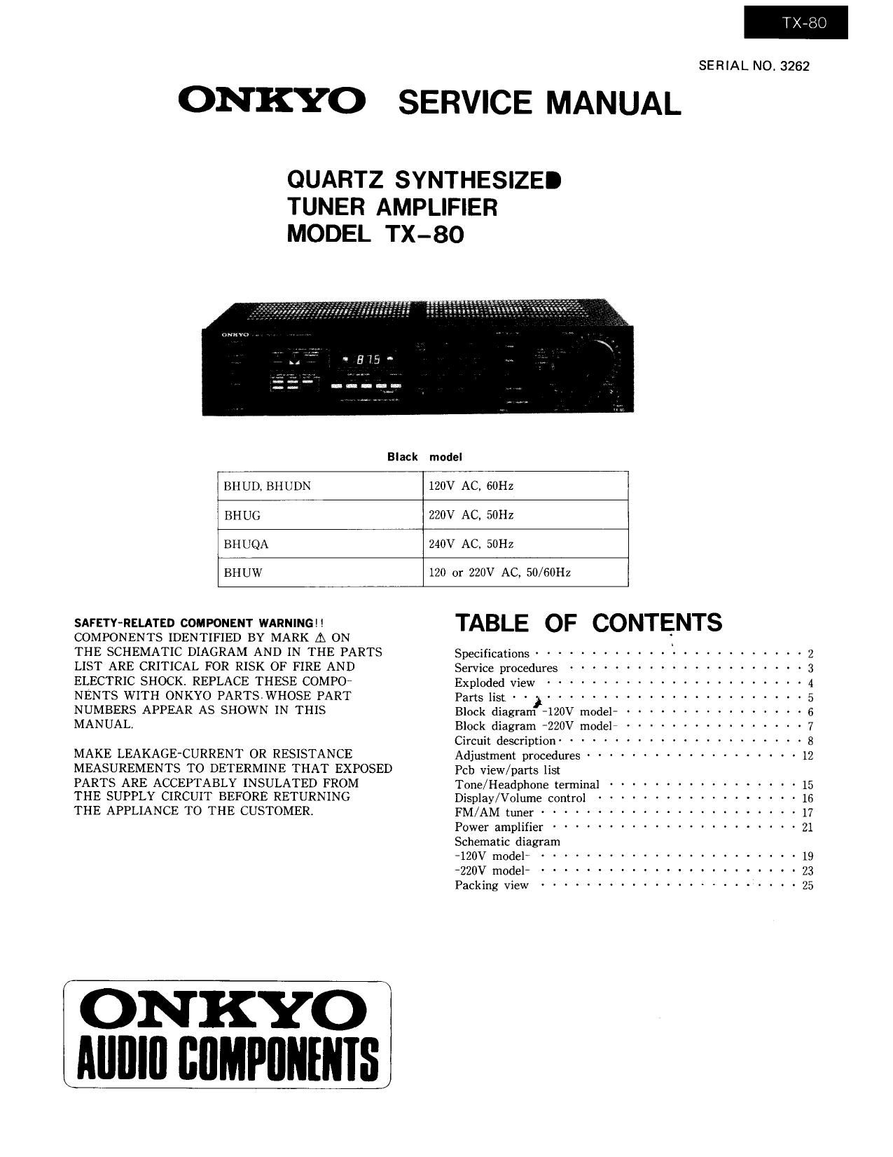
Onkyo TX 80 Service Manual

Extracted text from Onkyo TX 80 Service Manual (Ocr-read)


Page 1

TX-B

SERIAL NO. 3262

ONKYO SERVICE MANUAL

QUARTZ SYNTHESIZEI
TUNER AMPLIFIER
MODEL TX-80

Black

model

BII UD, BH U DN

120V AC, 60Hz

BHUG 220V AC, 50Hz
BHUQA 240V AC, SOHZ
BHUW 120 or 220V AC, 50/60H2

SAFETY-RELATED COMPONENT WARNING! !
COMPONENTS IDENTIFIED BY MARK [A ON
THE SCHEMATIC DIAGRAM AND IN THE PARTS
LIST ARE CRITICAL FOR RISK OF FIRE AND
ELECTRIC SHOCK. REPLACE THESE COMPOT
NENTS WITH ONKYO PARTSWHOSE PART
NUMBERS APPEAR AS SHOWN IN THIS
MANUAL.

MAKE LEAKAGE-CURRENT OR RESISTANCE
MEASUREMENTS TO DETERMINE THAT EXPOSED
PARTS ARE ACCEPTABLY INSULATED FROM

THE SUPPLY CIRCUIT BEFORE RETURNING

THE APPLIANCE TO THE CUSTOMER.

ONKYO
Mllllll BUMPIINENIS

TABLE OF CONTENTS

Specifications ........................ 2
Service procedures ..................... 3
Exploded view ....................... 4
Parts list . . ....................... 5
Block diagram ~120V model ---------------- 6
Block diagram ~220V modeli --------------- 7
Circuit description ...................... 8
Adjustment procedures ------------------- 12
Feb view/parts list

Tone/ Headphone terminal ---------------- 15
Display/Volume control ----------------- 16
FM/AM tuner -------------------- 17
power amplifier ...................... 21
Schematic diagram

~120V model- ....................... 19
T220V modeli

Packing View ....................... 25

O

Page 11

3. Frequency indicator circuit

wNvROL

E
z
3
o
u

v »;

5ND|I

DECODE R

an: :2 dz .2 V2 92 u m a a: u :1 ya i/O
- 0

{ l
M

LAvcn

Bmlvy to em mi IF UFFSEI ROM

TD6301AP block diagram

Pin No. Terminal Description

1 L/D Output indication switching input terminal:Fluorescent display at the low level,and
LED display at the high levell

2 Data Tuned frequency data input tenninal:lnput from the system controller LSI to the
serial.

3,4 CKl Tuned frequency data input control timing input terminal:

CKZ Transferred simultaneously with data from the system controller LS].

5 I/O Segment drive output terminal:Sets the number of display digit for FM(100MHz) and
AM(1000kHz) reception

6'12 3333 Seven segment drive output tenninal:Sets the number of display digit for FM(10MHz)
and AM(100kHz) reception.

13V a27g2 Seven segment drive output terminal:Sets the number of display digit for FM(1Ml-lz)

15*20 and AM(10kHz) reception

21*27 al-gl Seven segment drive output terminal:Sets the number of display digit for FMilOOkI-Iz)
and AM(1kH2) reception.

14 Vcc Power source teminal

28 Gnd Ground

_11_