Onkyo TX 7000 Service Manual

This is the 21 pages manual for Onkyo TX 7000 Service Manual.
Read or download the pdf for free. If you want to contribute, please upload pdfs to audioservicemanuals.wetransfer.com.

Page: 1 / 21
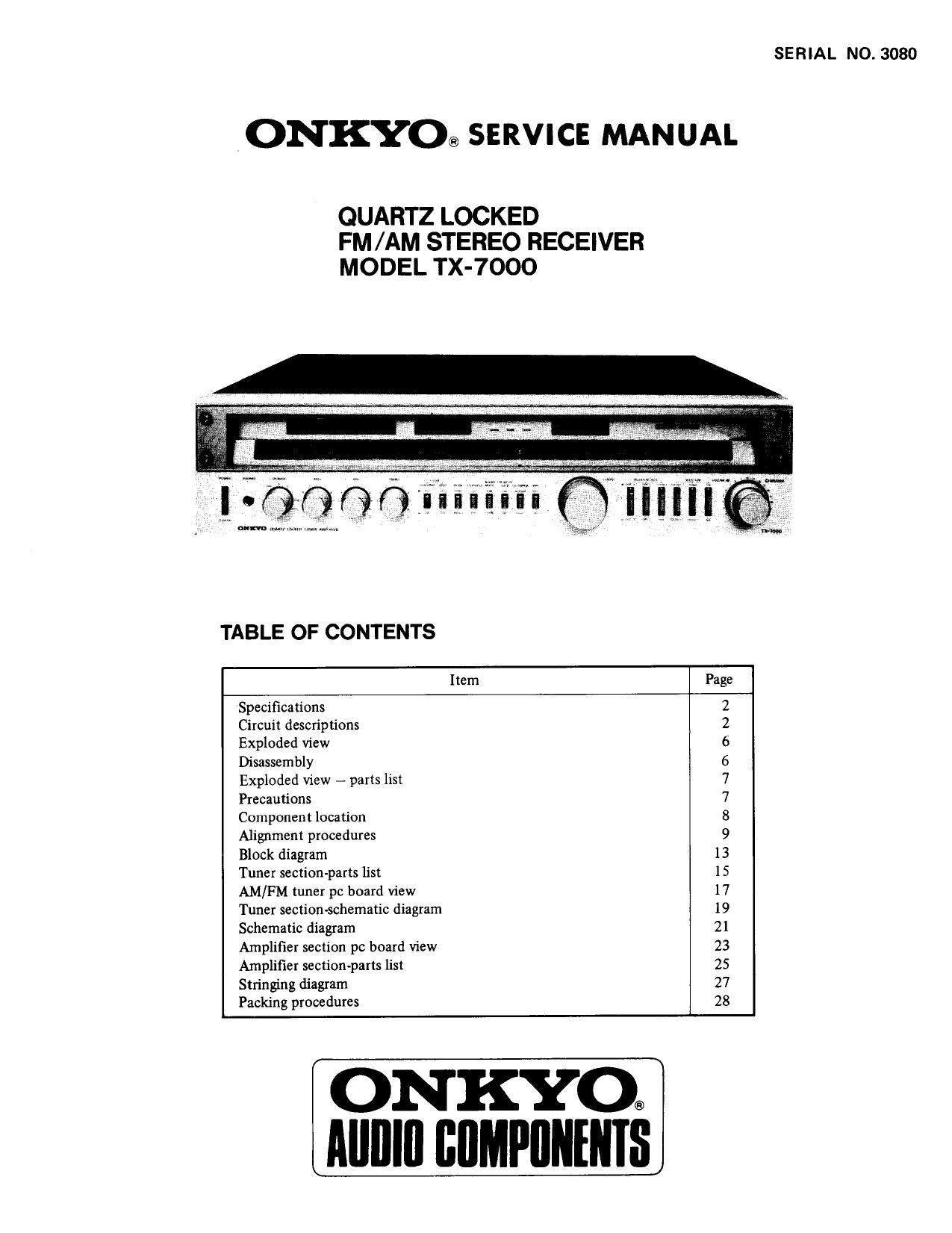
Onkyo TX 7000 Service Manual

Extracted text from Onkyo TX 7000 Service Manual (Ocr-read)


Page 1

SERIAL NO. 3080

.ONKYO® SERVICE MANUAL

QUARTZ LOCKED
FM/AM STEREO RECEIVER
MODEL TX-7000

TABLE OF CONTENTS

Item Page
Specifications 2
Circuit descriptions 2
Exploded view 6
Disassembly 6
Exploded View # parts list 7
Precautions 7
Component location 8
Alignment procedures 9
Block diagram 13
Tuner section-parts list 15
AM/FM tuner pc board view 17
Tuner section-schematic diagram 19
Schematic diagram 21
Amplifier section pc board view 23
Amplifier section-parts list 25
Stringing diagram 27
Packing procedures 28

ON KYO®
Alllllll BflMPflNlNIS

Page 2

SPECIFICATIONS

AMPLIFIER SECTION
Output Power:

Total Harmonic
Distortion:

IM Distortion:
Damping Factor:
Frequency Response:
RIAA Deviation:

Sensitivity 81
Impedance:

Phono Overload:

Signal-to-Noise Ratio:

Residual Hum 81 Noise:

Tone Controls:

Filters:
Loudness (-40 dB):

TUNER SECTION

FM:
Tuning Range:
Usable Sensitivity:

50 dB Ouieting
Sensitivity:

90 watts per channel, min, RMS,
at 8 ohms both channels driven,
from 20 Hz to 20,000 Hz with no
more than 0.02% total harmonic
distortion.

0.02%, at rated power
0.018% at 1 watt output
0.02% at rated power
0.018% at 1 watt output

50 at 8 ohms

10 Hz - 30,000 Hz (:1 dB)
20 Hz - 20,000 Hz ($0.3 dB)

Phono: 2.5 mV, 50 kohms
Tape Play: 150 mV, 50 kohms
Tape Rec: 150 mV, 3.5 kohms
(PH)

200 mV RMS at 1 kHz, 0.02%

T.H.D.

Phone: 76 dB (IHF A weighted,
1 watt output, 5 mV
input)

86 dB (A weighted, 10
mV input)
Tape: 80 dB (IHF Aweighted,

1 watt output, 0.5 V

input)

96 dB (A weighted)
0.5 mV at min. volume level

(A weighted)

Bass: :12 dB atIOO Hz
Mid: i5 dB at 1 kHz
Treble: :10 dB at 10 kHz
High: 6 kHz, 12 dB/oct.
Subsonic: 10 H2, 12 dB/oct.

+8 dB at 40 Hz
+5 dB at 20 kHz

88 - 108 MHz

Mono: 9.8 dBf, 1.7uV
Stereo: 17.2 dBf, 4.01.1V
Mono: 14.7 dBf, 3.011V

CIRCUIT DESCRIPTIONS

TUNER SECTION

Capture Ratio:
Image Rejection Ratio:
IF Rejection Ratio:

Spurious Rejection Ratio:

Signal-to-Noise Ratio:

Alternate Channel Att:
AM Suppression Ratio:
Harmonic Distortion:

Frequency Response:
Stereo Separation:

Muting Level:
Stereo Threshold:
Quartz Lock Level:

AM:

Tuning Range:

Usable Sensitivity:
Image Rejection Ratio:
IF Rejection Ratio:
Signal-to-Noise Ratio:
Harmonic Distortion:
GENERAL

Power Supply:
Outputs:

Inputs:

Antennas:

Semiconductors:
Dimensions (WxHxD):

Weight:

Stereo: 35 dBf, 310V
1.3 dB

90 dB

100 dB

95 dB

Mono: 74 dB
Stereo: 68 dB
70 dB

55 dB

Mono: 0.15%
Stereo: 0.3%

30 Hz -15,000 Hz (11.5 dB)
40 dB at 1 kHz
34 dB at 100 Hz ~ 10,000 Hz
17.2 dBf, 411v
17.2 dBf, 414v
17.2 dBf, 411v

525 - 1,620 kHz
250V

45 dB

40 dB

40 dB

0.8%

AC 120 volts, 60 Hz
Speaker A, B, C, Phones, Tape Rec
Out 1 81 2, EPS OUT (PRE OUT),
AC Outlets (Switched x 1,
Unswitched x 2)
Phono 181 2, Tape Play 1 81 2,
EPS IN (MAIN IN), FM and
AM Antennas
FM: 300 ohms balanced and
75 ohms unbalanced
AM: built-in ferrite core
antenna and external
terminal
2 FETs, 63 transistors, 18 I05,
47 diodes
575 x146 x 462 mm
22-5/8" x 5-3/4" x 18-3/16"
19 kg, 41.8 lbs

Specifications and features are subject to change without notice.

A major feature of the FM tuner section of the TX-7000 is the Quartz Locked system which detects any difference in fre-
quency between the IF signal and the reference signal generated by the crystal osillator.
Another important feature of this equipment Is the Touch sensor circuit.

When the TUNING knob is touched by hand, the quartz locked circuit is deactivated, permitting the tuned frequency to be
freely varied just as in conventional equipment.

POWER AMPLIFIER SECTION
A major feature of the power amplifier section is the servo operational amplifier system.

_22

Page 20

CIRCUIT NO. PARTS NO. DESCRIPTION

Q508. Q608 2211633 or 28C2229(0) or
2211634 25C2229(Y)
Q509, Q609 2211353 or 2SA949(O) or
2211354 28A949(Y)
Q510, Q610 2200863 or 23C2238(0) or
2200864 25C2238(Y)
Q511, Q61] 2200873 or 2SA968(O) or
2200874 28A968(Y)
Q513, Q613 2201194 or 288706(R) or
2201195 2513706 (Q)
Q512, Q612 2201204 or 2SD746(R) or

2201205 ZSD746(Q)

CAUTION: Replacement for power, complementary and drive
transistor, if necessary, must be made from the same
beta group (HFE) as the original typei

ICs
Q514, Q614 222502 NJM-4558DX
Q515, Q615

Diodes
D501, D601 4000022 VD1212
D502-D504 223105 181555
D602-D604

Coils
L501, L601 231001 S-1.3B

Capacitors
C501, C601 392880227T 2.2uF, 50V, LL
C506, C606 352780109T lpF, 50V, Elect.
C509, C609
C510,C610 352780339T 3.31.11, 50V,Elect.
C517, C518 392852207T 221417, 25V, LL
C617, C618
C519, C520 352753319 330uF, 25V, Elect.
C521, C621 352780339T 3.3uF, 50V, Elect.
C522, C523 352770229T 2.2uF, 63V, Elect.
C622, C623
C524, C624 352770479T 4.7,.F, 63V, Elect,
C526, C626 352770479T 4.7uF, 63V. Elect.

Resistors
R517, R617 5221019 N10HR47OBE, Semi-fixed
R531, R631 441524714 47012, VzW, Metal oxide film
R532, R632

STRINGING DIAGRAM

CIRCUIT NO. PARTS NO. DESCRIPTION

R533, R633 441621514 1509.1W. Metal oxide film
R534, R634 4000069 RGC33K0.22x2, Metal plate
R535, R635
R536, R636 4000070 RGC3K-0,18, Metal plate
R537, R637
R538, R638 4000071 RGC3K-1.0, Metal plate
R539, R639 451731004 10H, 2W, Metal
R540, R640 451530564 5651, ViW, Metal
R542, R642 5221007 R-HK2.2KB, Semi-fixed
Radiator
27160011

THERMAL DETECTOR PC BOARD (NACC-874) 7
PARTS LIST '

CIRCUIT NO. PARTS NO, DESCRIPTION

0507, (2607 2211255 or ZSC1815(GR) or

2211256 ZSC1815(BL)

LAMP PC BOARD (NAPL-747c/NAPL-879) -
PARTS LIST

CIRCUIT NO, PARTS NO. DESCRIPTION

PL801 210095 PLé.3V, 0,3A, Lamp
210088 PL24V, 0.08A, Lamp

METER ILLUMINATION LAMP PC BOARD
(NAPL-787) - PARTS LIST

CIRCUIT NO. PARTS NO. DESCRIPTION

PL803-PL805 210054B PL6.3V, 0125A, Lamp
NOTES:
1. DC voltage are measured with V.T1V1Mi to chassis at no signal
applied.
2. Capacitor LL: Low leakage current type electrolytic
capacitor
ST: Polystyren film capacitor

1. Close the variable capacitor complete and tie the dial cord to the spring of the drum.
2. Thread the dial cord in the direction of arrow from (D to © and wind the dial cord three turns around the tuning shaft

counter - clockwise.

3. Thread the dial cord in the direction of arrow from © to @ .

4. Wind the dial cord 1% turns around the dial drum.