Onkyo TX 440 Service Manual

This is the 12 pages manual for Onkyo TX 440 Service Manual.
Read or download the pdf for free. If you want to contribute, please upload pdfs to audioservicemanuals.wetransfer.com.

Page: 1 / 12
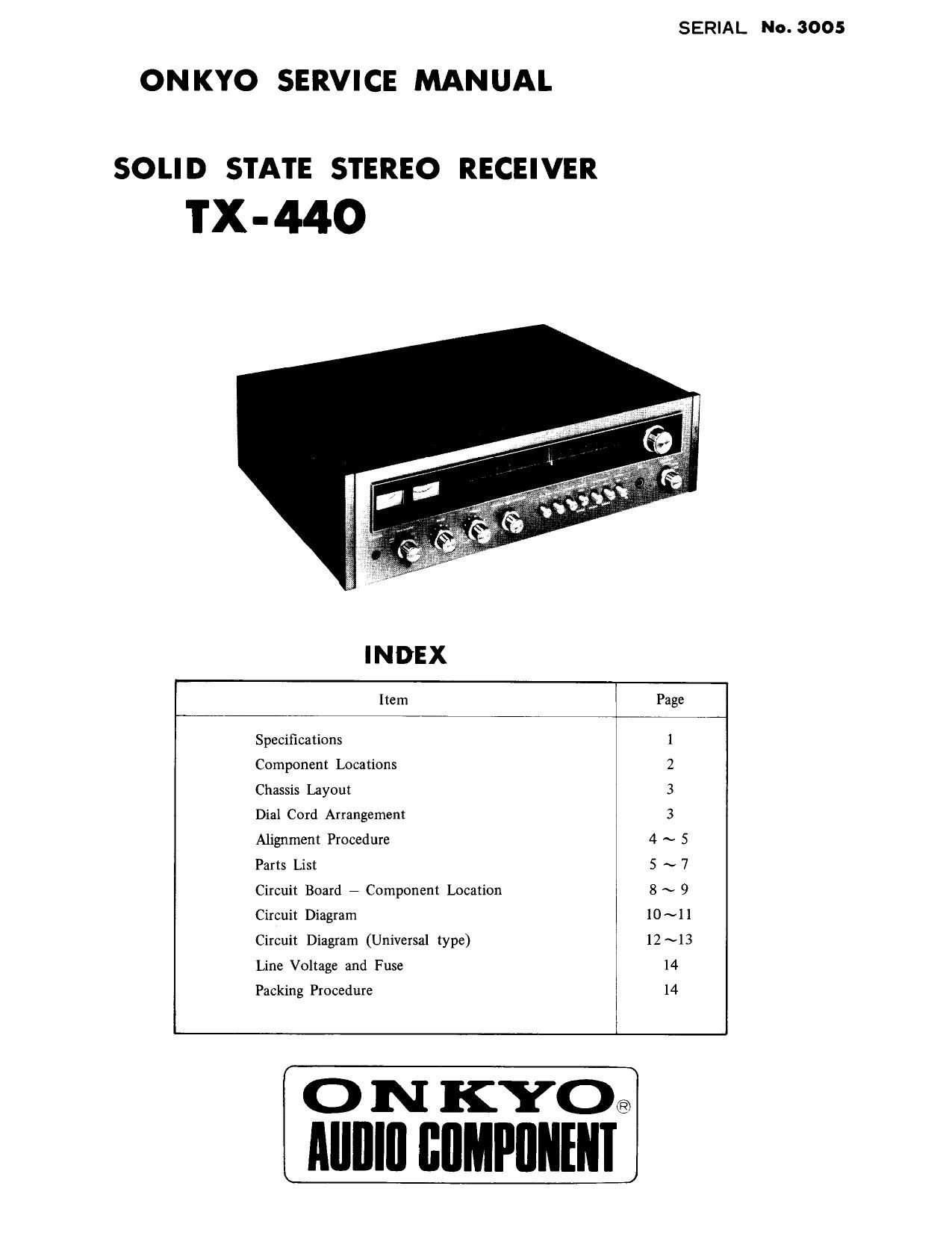
Onkyo TX 440 Service Manual

Extracted text from Onkyo TX 440 Service Manual (Ocr-read)


Page 1

SERIAL No. 3005

ON KYO SERVICE MANUAL

SOLID STATE STEREO RECEIVER

TX-440

INDEX

Item Page
Specifications i
Component Locations 2
Chassis Layout 3
Dial Cord Arrangement 3
Alignment Procedure 4 ~ 5
Parts List 5 ~ 7
Circuit Board - Component Location 8 ~ 9
Circuit Diagram 10~ll
Circuit Diagram (Universal type) 12 ~13
Line Voltage and Fuse 14
Packing Procedure 14

Alllllll flflMPIINENI

Page 6

|
CONNECT SIGNAL SET SIGNAL CONNECT OUTPUT SET RADIO ADJUST
STEP SOURCE T0 T0- INDICATOR T0- DIAL TO- ADJUST FOR REMARKS STEP
Osilloscope No noise Signals m
to- Tuned Variable when damned nul necessarily
ll across and Detuned Resistor but less Sqnelching
15 SPEAKER" to Signal lelooml effective for by turning 16
terminal Signal Output R713
when tuner] counter .
clockmse
17 Set Radio Selectcr Switch to "RM AUTO Set Muiing Switch to OFF 17
98MHz V. T. V, M. 10- L201
u (Pilot Sigl across "TP3" Tuned to NMC-4-10 Maximum
8 19KHz 10%) terminal Signal 13
lmv input (NAM-224)
98an v. T, v. M. m-
lPilot Sign across L202
19 ll 1910-11 10%) "SPEAKER" " NMC5-9 Maximum 19
1K.Hz lermlnal
R ch 90% [R ch)
QSMHz Retouch slightly
(Pilot Sig. (Repeal Steps
IQKHz 10%) Variable 20 and 21
20 1 Main 81 Sub l " Resistor Minimum an necessary 20
Sig, (R ch} R223 110m)
1KHz
L ch 90%
2 R ch 90% (L clil 2
PARTS llST
CIRCUIT No. DESCRIPTION SPECIFICATION QTY STOCK NO.
U1 FM Front End FL-r322U 1 240005
U2 Power Amp assembly NAPA-l98C l 13889598C
U3 Pie-Amp assembly NAAF7222a 1 13889522A
U4 IF & MPX assembly NAIM-224 1 13899524
U5 Power Supply assembly NAPS-225 1 13889525
PLSOl, PL802 Pilot Lamp 6.3V0.USAW73 2 210015
PL803 - PLSDB Pilot Lamp 6.3V0.25A 6 210012
T901 Transformer-Power NPT~555D 1 230046
L001 Coil-Antenna NMA-2508 1 232023
T001 Transformevaalloon NBLN-l 1 233026
C903. C904 Capacitor-Electrolytic CE62W35V470011F 2 350403OA
C905 Capacitor-Electrolytic CE62W50V470pFX2 1 3504037A
C901 Capacitor-Polyester (UL) UL200V0.0111F(M) 1 3504012
8801 Switch-Rotary NRSM-486-30Y-A 1 250106
5802 Switch-Rotary NRS-227-30Y7AP 1 250188
M101 Tuning Indicator NlND-OSOOS29 1 243020 Strength meter
M102 Tuning Indicator NIND70250530 1 243021 Tuning meter
Dial Plate 1 270565
Back Plate 1 270211-1
Drive Shaft 1 270218
Dial Pointer 1 270273
Dial Pointer Case 1 270172-2
Pointer Holder AS 1 270173

Page 12

LINE VOLTAGE AND FUSE

The model TX-440 is available in two models: one model
operates only on 120V, and the other operates on one of
the four line voltages, 110V, 120V, 220V and 240V. If
your TXr440 is the latter model, set the unit to proper
line voltage by following the procedure described below.

CHANGING LINE VOLTAGE SETTING AND FUSE

To remove the fuse, turn the fuse cap located on the line
voltage selector in the direction of the arrow.

Put the fuse
plug back so that the proper line voltage marking can be

Then remove the fuse plug from the unit.

seen through the cut in the edge of the plug.

Whenever the position of the selector is changed, check the
rating of the fuse. A 1.5A fuse is to be used for either
220V or 240V operation and a 3A fuse for 110V or 120V

0 peration .

PACKING PROCEDURE

1. Tighten SPEAKER terminals by a hand.
Clean an AMP BOX assembly, attending to your finger-

E"

prints.
. Set a SENSITIVITY SWITCH to center (2.4mV).
. Clean a REAR PANEL and a RADIATOR.
. Insert SHORTED PIN into PHONO-l, 2 terminals.
. Wrap a POWER CORD with 21 AC CORD WRAPPER
and bind it with a rubber band.
7. Wrap unit with a AMP COVER and attach a SIDE PAD
to both sides.
8. Put in a CARTON BOX and make sure the front marks
of the carton matches the unit front.
9. Put an ACCESSORY BAG including an INSTRUCTION
BOOKLET, WARRANTY CARD etc in the box.
10. Close the CARTON BOX and seal.

mun-bu:

_14-

FUSE REPLACEMENT
Mien the fuse blows, remove the fuse cap and replace the

fuse with a new one. See Fig. 1.
If you replace the fuse, use the fuse of the specified
capacity.

AC fuse 2A timelag type

Pilot lamp fuse 3A timelag type

Speaker protective fuse-3A standard type.

COIN y
l q» l FUSE PLUG
/ .?5 FUSE
FUSE CAP

Fig. l

P . SS LABEL


gfi SERIAL SHEET

CAUTION LABEL

AMP COVER

:7

L_l_l
<2:

SIDE PAD

CIRCUIT


ACCESSORY BAG

CARTON B O X