Onkyo TX 35 Service Manual

This is the 32 pages manual for Onkyo TX 35 Service Manual.
Read or download the pdf for free. If you want to contribute, please upload pdfs to audioservicemanuals.wetransfer.com.

Page: 1 / 32
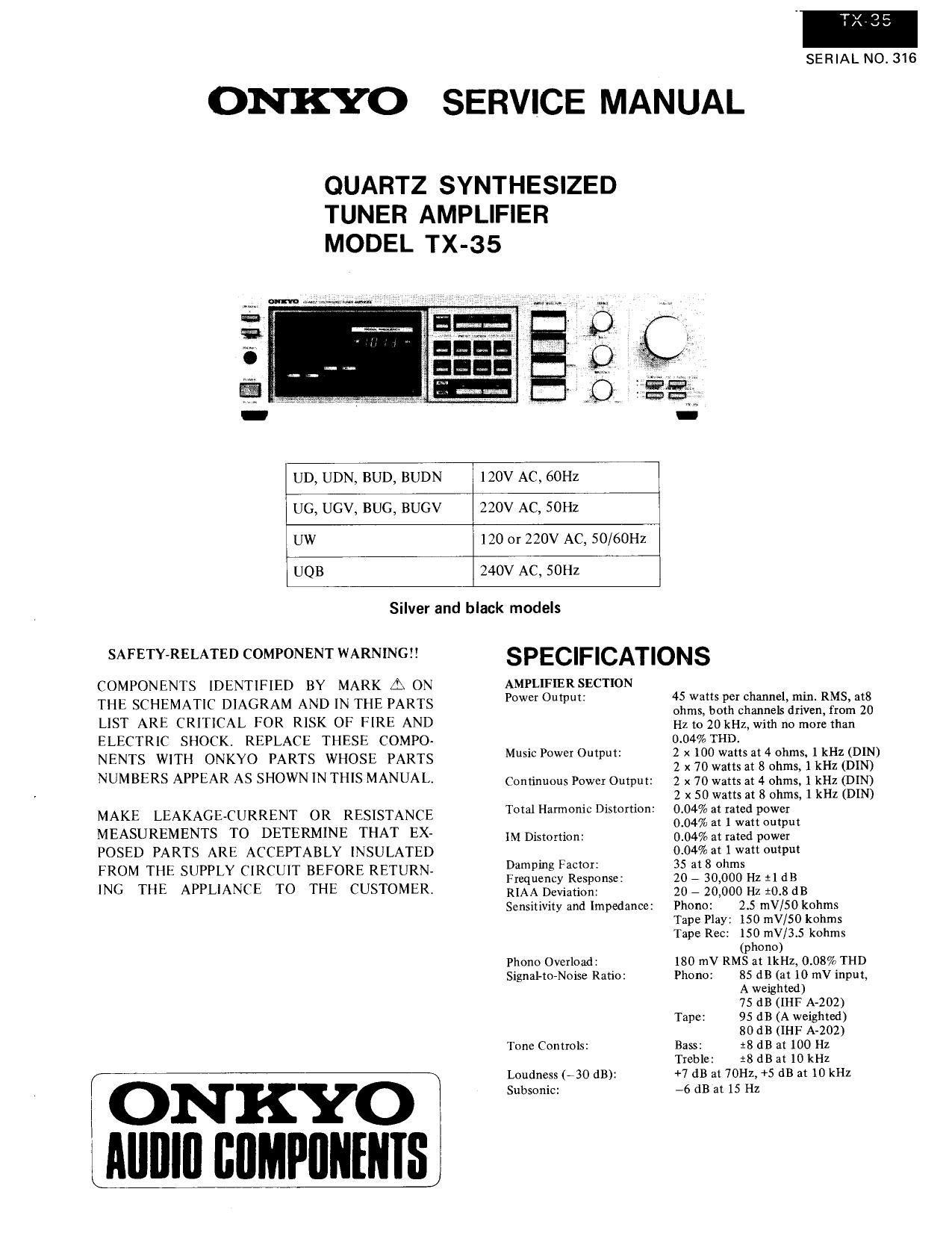
Onkyo TX 35 Service Manual

Extracted text from Onkyo TX 35 Service Manual (Ocr-read)


Page 13

5. PLL tuned circuit

as PSC
FMl I " l
a l '0 Prescaler 37 Swarm,
r .. , ,, 7 7-4
2153].? 5 1/30 or 1/32" counter
, 1 , . r
7"77 l "V 7
1 1
l (in/:2, , 37547 - FM/AM A-Progvammablel 'r Phase
mm, to selector ; divrder
_, i , ,,

7,, , 1
Low pass LED
filler

controller LSI

omnaramrk

' 72mm
crystal
oscrtllaror
,
Rererence
_, frequency
dwlder

tr

(fig. 6)

FSC

OUT I

2 OUT?

[fig 7) TD6104P (Prescalerl

A block diagram ofthe tuned circuit of the PLL is shown in
figer 61

Operation during AM reception

The reception frequency is applied to the programmable
divider where it is divided to UN and output as fv, This is
applied to the phase comparator where it is comparated
with frequency reference fr (9kHz for G/W model and
10kHz for D model). If fr and fv differ, Eo equal to the dif-
ference in frequency is output. Since error output E0 is a
pulse waveform, it is passed through the low pass filter to
change it into DC voltage VD, which is applied to the varia-
ble capacitor diode in the front end to change the reception
frequency. This continues until fv and fr are the same and
E0 =0.

Operation during FM reception

The pulse swallow method is used in the prescaler of
this unit, In this type ofprescaler, a supplementary number

6. Frequency indicator circuit

.i m :1 a: .v n gl

.2o2 :2 e222 i2 92 .3 m :3 d3 .3 l1g3

Emmy to 8CD .1 IF OFFSEY ROM

(fig. 8] TD6301AP block diagram

(changed according to the program code input) and the
divided reception frequency from the prescaler are com-
bined in the control counter and the prescalers division
factor is switched 1/30 or 1/32 according to external
control (1/32 when the PSC terminal is I! and 1/30 when
it is L").

The station oscillator frequency is applied or the program-
mable divider, but the programmable divider has en upper
frequency limit of only 3OMHZ, so the pulse swallow-type
prescaler which can be used up to 150 MHZ, is inserted for
division to 1/Np;

The signal is applied to the programmable divider and
divided to 1/N. The result is compared with a 25kHz
frequency reference in the phase detector and the error
is output as E0 until a match is obtained as in AM opera-
tion.