Onkyo TX 27 Service Manual

This is the 29 pages manual for Onkyo TX 27 Service Manual.
Read or download the pdf for free. If you want to contribute, please upload pdfs to audioservicemanuals.wetransfer.com.

Page: 1 / 29
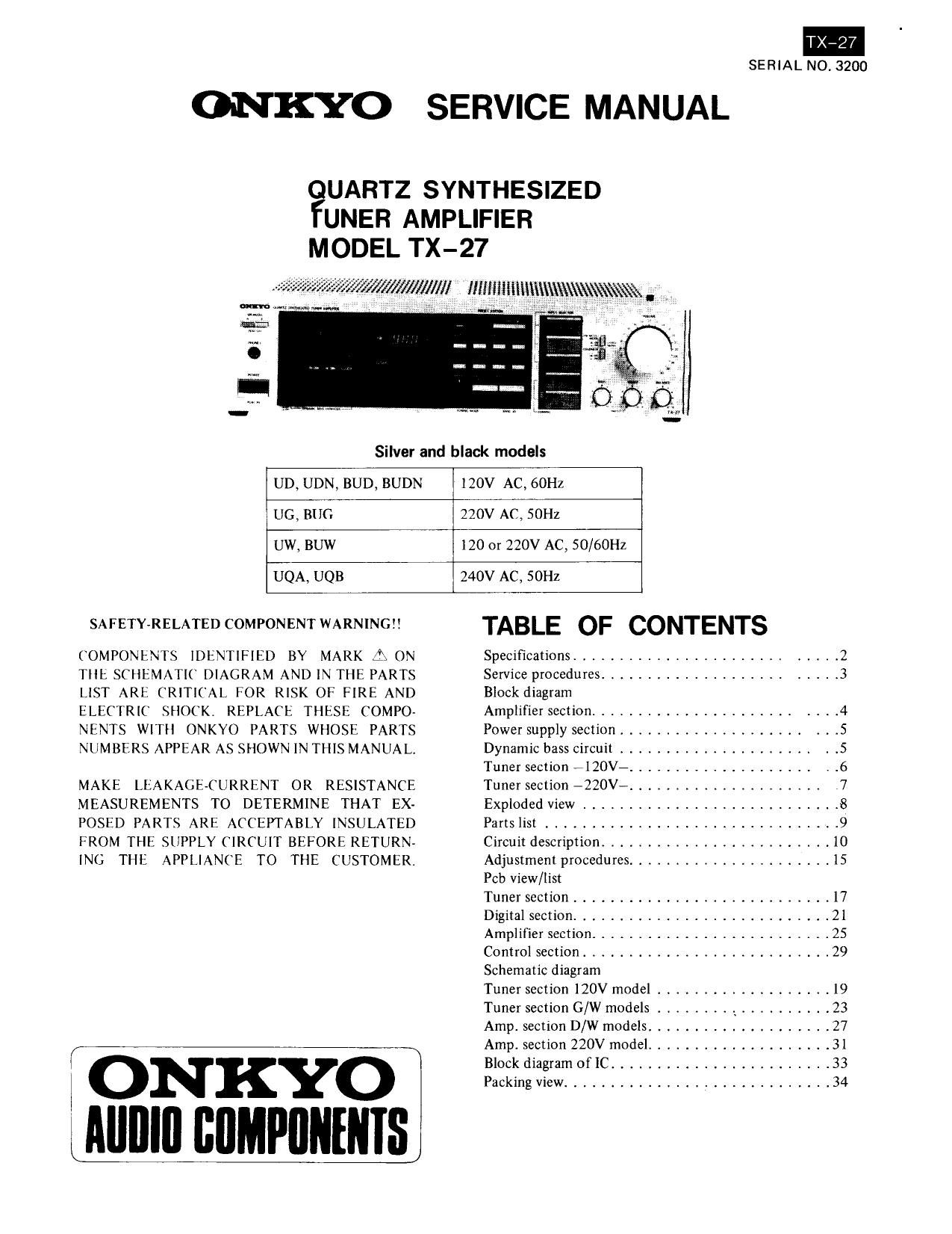
Onkyo TX 27 Service Manual

Extracted text from Onkyo TX 27 Service Manual (Ocr-read)


Page 1

TX-27
SERIAL NO. 3200

ONKYO SERVICE MANUAL

UARTZ SYNTHESIZED
UNER AMPLIFIER
MODEL TX-27

WWW/Ml IIIIIIIIIIIIIIIIIIA\\\\W\W%.

Silver and black models

UD, UDN, BUD, BUDN

120V AC, 60Hz

UG, BUG

220V AC, 501-12

UW, BUW

120 or 220V AC, SO/bOHZ

UQA, UQB

240V AC, SOHZ

SAFETY-RELATED COMPONENT WARNINGII

COMPONENTS IDENTIFIED BY MARK ON
THE SCIIEMATK DIAGRAM AND IN TIIE PAR TS
LIST ARE CRITICAL FOR RISK OF FIRE AND
ELECTRIC SHOCK, REPLACE THESE COMPO»
NENTS WITII ONKYO PARTS WHOSE PARTS
NUMBERS APPEAR AS SHOWN IN THIS MANUAL.

MAKE LEAKAGECURRENT OR RESISTANCE
MEASUREMENTS TO DETERMINE THAT EX-
POSED PARTS ARE ACCEPTABLY INSULATED
FROM THE SUPPLY CIRCUIT BEFORE RETURN-
ING THE APPLIANCE TO THE CUSTOMER.

IONKYO
IAIIIIIII IIIIMPIIIIIIIISI

TABLE OF CONTENTS

Specifications ............................ 2
Service procedures ......................... 3
Block diagram

Amplifier section ...................... , 4
Power supply section .................... . .5
Dynamic bass circuit ..................... . .5
Tuner section 7120V7 .................... V .6
Tuner section -220V- ..................... 7
Exploded View ........................... 8
Parts list ................................ 9
Circuit description ......................... I0
Adjustment procedures ...................... 15
Feb view/list

Tuner section ............................ 17
Digital section ............................ 21
Amplifier section .......................... 25
Control section ........................... 29
Schematic diagram

Tuner section I20V model ................... I9
Tuner section G/W models r I _ . . . I . z .......... 23
Amp. section D/W models .................... 27
Amps section 220V model .................... 31
Block diagram of IC ........................ 33
Packing view ............................. 34

Page 5

-POWER SUPPLY SECTION-
-120V MODEL- -220V MODEL-

H t8! 36 5V --+ +5136,5V

+82 18V -i-3215V

_o/ ONZST Hazzov N T +542 V
VOUAGE VgLTSAG U
-52 -iBV -BZ lav
eat-38.2V 451-38. 2V
090109 I
CONST 9» B3 COSST ->v 33
VOLTAGE 12v VOLTAGE 12v

To FLUORESCENT To FLUORESCENT
INDICATOR INDICATOR
TUBE TUBE

-DYNAMIC BASS EXPANDER-

0 POWER OUTPUT
INPUT 0
AMPLI
R543
LEVEL
0523 0524 D521 , 0525
MIX -FILTER D522 ' FILTER
BUFFER AMPLI RECTIFIER CONTROL
_l
other channel other channel

In earlier super base systems, only the frequencies about 70Hz were boosted by about 4dB to expand the playback frequ-
ency response to enable playback of the super low region. However. when there was no input signal, the above frequency
response resulted in deterioration in the S/N ration in the 70Hz region. This problem has been overcome by the dynamic
bass expander where the 70Hz boosted level is varied according to the input signal level. That is, the frequency response
remains flat when no input signalis applied, but is boosted at the 70Hz region to the specified level when the input signal
exceeds a certain level. The left and right channel input signals from the INPUT terminals are mixed by Q523 and pass
through the level volume and filter amplifier. The signal is rectified by D551 and D552, and the resultant DC component
control signal is applied to the gate of 0525. When the input signal is at a adequate level, Q525 is turned on and the super
base crrcuit of power amplifier is controlled by the input signal