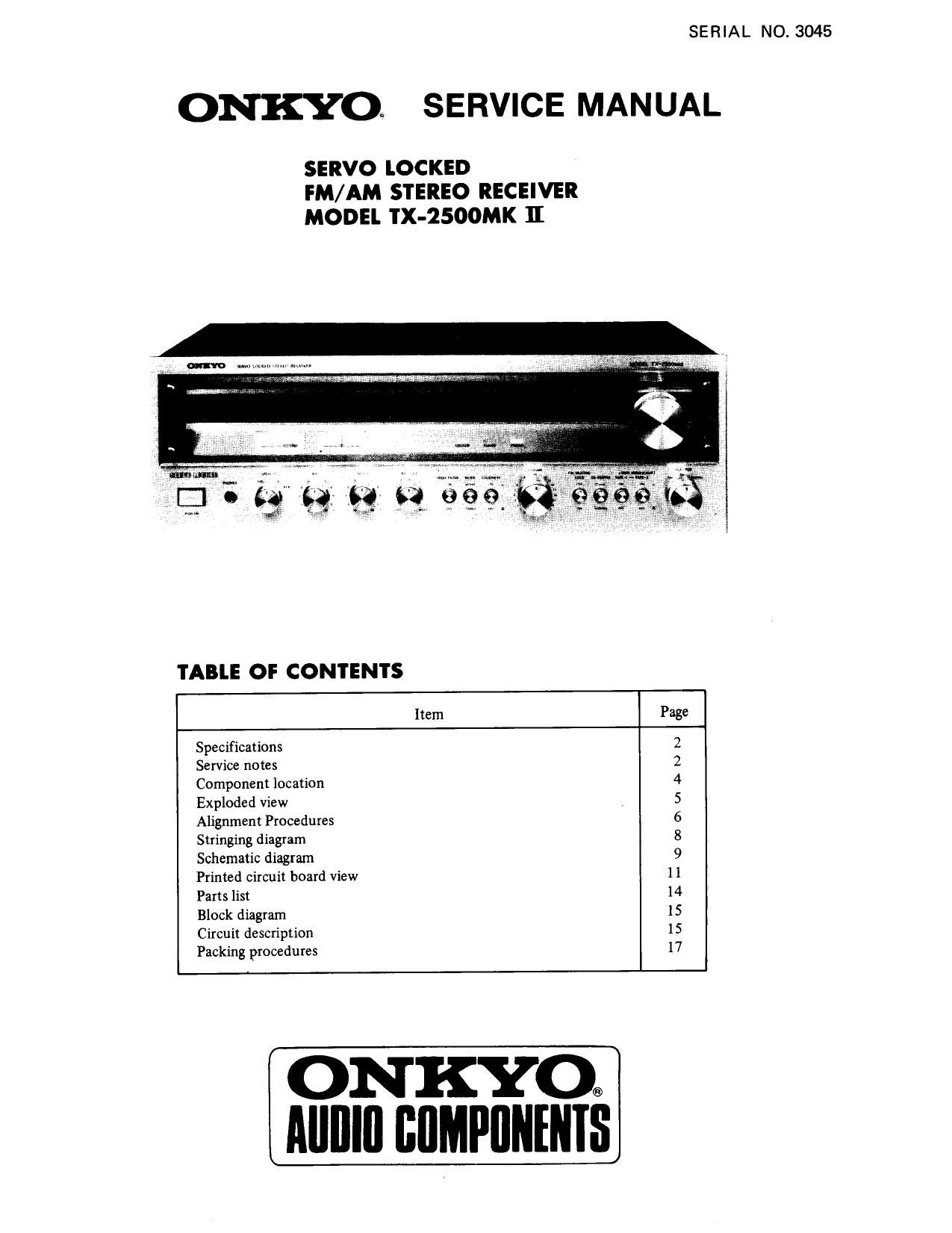
Onkyo TX 2500 MK2 Service Manual
This is the 13 pages manual for Onkyo TX 2500 MK2 Service Manual.
Read or download the pdf for free. If you want to contribute, please upload pdfs to audioservicemanuals.wetransfer.com.
Extracted text from Onkyo TX 2500 MK2 Service Manual (Ocr-read)
Page 1
SERIAL NO. 3045
ONKYOE SERVICE MANUAL
SERVO lOCKED
IM/AM STEREO RECEIVER
MODEL TX-2500MK II
TABLE OF CONTENTS
Item Page
Specifications 2
Service notes 2
Component location 4
Exploded View 5
Alignment Procedures 6
Stringing diagram 8
Schematic diagram 9
Printed circuit board view 11
Parts list 14
Block diagram 15
Circuit description 15
Packing procedures 17
ON KYO®
AIIIIIII IIIIMPIIIIIIIIS
Page 2
SPECIFICATIONS
Amplifier section
Power Output
Total Harmonic
Distortion
1M Distortion
Damping Factor
Frequency Response
Sensitivity and
Impedance
Phono Overload
Treble Control
Bass Control
Signal to Noise Ratio
High Filter
Loudness (-30 dB)
Tuner section
Tuning Range
Usable Sensitivity
40 watts per channel, min. RMS,
at 8 ohms both channels driven,
from 20 Hz to 20 kHz, with no
more than 0.1% total harmonic
distortion.
0.1% at rated power
0.08% at 1 watt output
0.3% at rated power
0.1% at 1 watt output
40 at 8 ohms
20 ~ 30,000 Hz (:1 dB)
PHONO: 2.5 mV 50 kohms
TAPE PLAY: 150 mV 50 kohms
TAPE REC: 150 mV 3.5 kohms
(PHONO)
150 mVRMS at 1 kHz 0.1% THD.
110 dB at 10 kHz
:12 dB at 100 Hz
PHONO: 85 dB (at 10 mV input
IHF A network)
65 dB (IHF C network)
TAPE: ' 95 dB (IHF A network)
90 dB (IHF C network)
6 kHz 6 dB/oct.
+9 dB at 40 Hz
+5 dB at 20 kHz
FM:
AM:
FM mono:
FM stereo:
AM:
88 ~ 108 MHz
530 ~ 1605 kHz
11.2 dBf, 2 [1V
19.2 dBf, 5 14V
25 uV
50 dB Quieting
Sensitivity
Intermediate frequency
Capture Ratio
Image Rejection Ratio
IF Rejection Ratio
Spurious Rejection
Signal to Noise Ratio
ACA
AM Suppression Ratio
Harmonic Distortion
Frequency Response
Stereo Separation
Muting Level
Stereo Threshold
Locked Level
Timing Meter
General
Power Supply
Dimensions
Weight
Semiconductors
FM mono: 17.2 dBf, 4 V
FM stereo: 37.2 dBf, 40 V
FM: 10.7 MHz
AM: 455 kHz
FM: 2 dB
FM: 45 dB
AM: 45 dB
FM: 80 dB
AM: 30 (13
FM: 1/2 [F 80 dB
FM mono: 65 dB
FM stereo: 60 dB
AM: 40 dB
FM: 60 dB
FM: 50 dB .
FM mono: 0.2%
FM stereo: 0.4%
AM: 0.8%
FM: 30~ 15,000 Hz
+0.5, ~ 2 dB
FM: 37 dB at 1 kHz
30 dB at
100 ~ 10,000 Hz
FM: 14.7 dBf, 3 11V
FM: 14.7 dBf, 3 uV
FM: 14.7 dBf, 3 uV
Signal strength & Center tuning
AC 120 volts 60 H1130 watts
19"W x 6-5/16"H x 14-5/8"D
483mmW x 160mm}! x 371mmD
25.3 lbs. 11.5 kg.
1 FET, 30 Transistors, 8 ICs,
28 Diodes
Specifications are subject to change without notice for improvement.
SERVICE NOTES
1. REPLACEMENT OF THE AC FUSE
1) Remove four screws holding leg and bottom board.
2) Remove five screws holding bottom board and side bracket.
3) Replace the AC fuse on the power supply p.c.b.
2. REPLACEMENT OF THE SPEAKER PROTECTION FUSE
1) Remove a screw holding the cover and back panel and remove the cover.
. 2) Replace the fuse with indica14-ampere types.
SPEAKER as:
4A
3. When replacing differential amplifier or push-pull amplifier transistors, be sure that transistors of one channel have the
same hpE ratings.
4. If the TUNED lamp does not turn off when you touch the tuning knob, this may be due to strong signals generated by
a nearby MW or SW broadcasting station. In this case, adjust the frequency of oscillator coil with L201 until the
TUNED lamp turn off.