Onkyo T 9090 Mk2 Service Manual

This is the 26 pages manual for Onkyo T 9090 Mk2 Service Manual.
Read or download the pdf for free. If you want to contribute, please upload pdfs to audioservicemanuals.wetransfer.com.

Page: 1 / 26
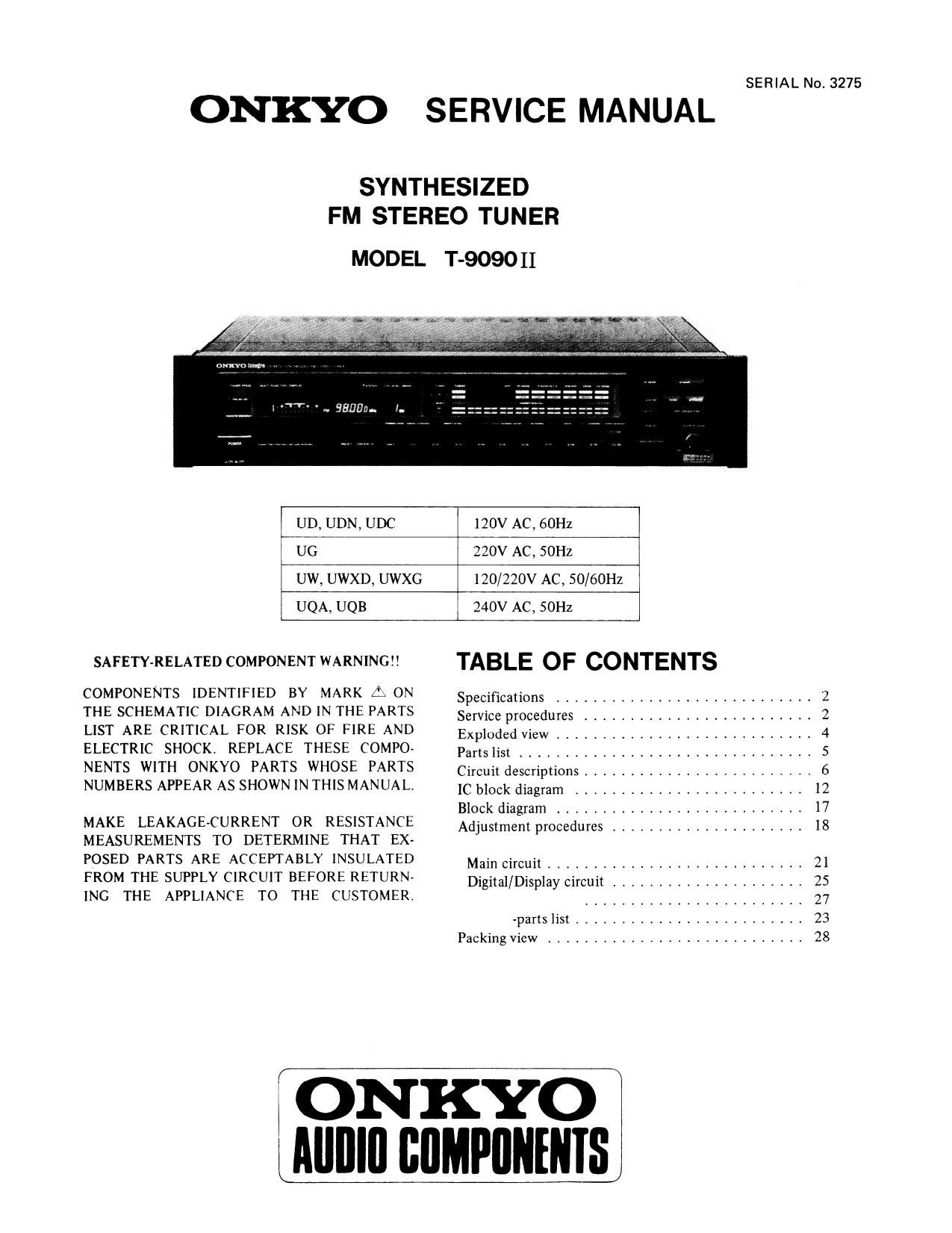
Onkyo T 9090 Mk2 Service Manual

Extracted text from Onkyo T 9090 Mk2 Service Manual (Ocr-read)


Page 1

SERIAL No. 3275

ONKYO SERVICE MANUAL

SYNTHESIZED
FM STEREO TUNER

MODEL T-9090 II

UD, UDN, UDC 120V AC, 60Hz

UG 23-0; AC, SOHZ
UW, UWXD, UWXG 120/220V AC, 50/60Hz
UQA. UQB 340V AC, 50Hz

SAFETYEELATED COMPONENT WARNINGYY TABLE OF CONTENTS

COMPONENTS IDENTIFIED BY MARK f; 0N

Specifications ............................ 2
THE SCHEMATIC DIAGRAM AND IN THE PARTS Service procedures ________________________ 2
LIST ARE CRITICAL FOR RISK OF FIRE AND Exploded View ............................ 4
ELECTRIC SHOCK REPLACE THESE COMPO- PaItSITSC ............................... 5
NENTS WITH ONKYO PARTS WHOSE PARTS CirCUit descriptions _______________________ 6
NUMBERS APPEAR AS SHOWN IN THIS MANUAL. IC block diagram _____________________ 12
Block diagram ........................... 17
MAKE LEAKAGECURRENT 0R RESISTANCE Adjustment procedures ..................... 18
MEASUREMENTS TO DETERMINE THAT EX-
POSED PARTS ARE ACCEPTABLY INSULATED Main circuit ___________________________ 21
FROM THE SUPPLY CIRCUIT BEFORE RETURN Digital/Display circuit ..................... 25
INC THE APPLIANCE TO THE CUSTOMER. ______________________ 27
-parts list ......................... 23
Packing View ............................ 28

ONKYO
LAIIIIIII IIIIMPIIIIIIIIS

Page 2

won

SPECIFICATIONS

Tuning Range:

87.5 7 108.0MHZ
(AUTO MODE SOkHz steps,
MANUAL MODE ZSkHz steps)

Usable Sensitivity: Mono: 0:8pV (S/N 26dB, 40kH7
Dev.) DIN
Stereo: 20.0}AV, (S/N 46dB,
40kHZ Dev.) DIN
SOdB Quieting Sensitivity: Mono: 15 .8dBf, 1.7uV
Stereo: 37.2dBf, 20pV
Capture Ratio: 1.0dB
Image Rejection Ratio: lUOdB
IF Rejection Ratio: lOOdB
Signal-to-Noise Ratio: Mono: 95dB (IHF)
Stereo: SSdB (IHF)
Selectivity: 80dB (:SOOkHz, IF: super
narrow)

SERVICE PROCEDURES

1. Replacing the lamp
This unit uses the lamp listed below.
Circuit no. Parts no. Desciption
0754 210064A PL 6.3V, ZSOmA. Dial
plate illumination

2. Safety-check out (D model)
After correcting the original service problem. perform
the following safety check before releasing the set to
the customer:
Connect the insulating-resistance tester between the
plug of power supply cable and tapping screw holding
the back panel and top cover.
Specification: 3.3MQ 110% at 500V

3. Change of De-emphasis

W models are equipped with a 50usec-75nsec selector
switch. This switch is located on the back panel, This
switch is set to 50nsec at the factory. but may have to
be reset to 75psec depending on the area where the unit
is used.

Europe: SOusec

USA; 75usec

AM Suppression Ratio:

Total Harmonic Distortion:

Frequency Response:
Stereo Separation:

Output Voltage:
Dimensions (W X H X D):

Weight:

60dB
Mono: 0.009% (IF: wide)
Stereo: 0.02% (IF: wide)

30 7 15,000Hz (+0.5dB, 71.0113)
SSdB at lkl-lz (IF: wide)

33dB at 70 7 10,000HZ (IF: wide)
0 7 1.5V

465 X 103 X 387mm

18-5/16" X 4-1/16" >< 15-1/4
8.5kg, 18.7lbsi

Specifications and features are subject to change without notice.

4. Change of voltage

W models are equipped with a voltage selector to con-
form with local power supplies This switch is located on
the back panel. Be sure to set this switch to match the
voltage of the power supply in your area before turning
the power switch on.
This switch is set to 220V at the factory. Voltage is
changed by sliding the groove in the switch with the
screwdriver to the right or left. Confirm that the switch
has been moved all the way to the right or left before
turning the power switch on.

5. Memory Preservation

This unit does not require memory preservation bat»
teries. A built-in memory power back-up system preser-
ves contents of the memory during power failures and
even when the unit is unplugged The unit must be plug-
ged in and the power switch turned on and off once in
order to charge the back-up systemi Note that since this
is not a permanent memory. the poWer switch must be
turned on and off a few times each month to keep the
back-up system operable. The period of time during
which memory contents are preserved after power has
last been turned off varies depending on climate and the
location and placement of the unit On the average.
memory contents are protected over a period of 3 to 4
weeks (a minimum of 2 weeks) after the last time
power has been turned off. This period is shorter when
the unit is exposed to very high humidity or used in an
area with an extremely humid climate.

Page 3

6. Procedures for replacement of flat packaged [Cs
1. Tools to be used:
(1) Soldering iron . . . . Grounded soldering iron 0
soldering iron with leak re
sistance of

more .

Form of soldering irons tip:

(2) Magnifyingglaas . . . for checking of finished
works

(3) Tweezers ....... for handling of 1C and
forming of leads

(4) Groundingring . . . . Countermeasure for electro-
static breakdown

(5) Nipper ......... for removing defective IC

(6) Small brush ...... for application of flux

2. Work Procedures:

(l) Remove the defective [C

Cut all leads of the defective IC one by one using

a nipper and remove the IC.

Clean the pattern surface of the PC board.

Get rid of the remaining leads and solder.

(3) Check and from the leads of the new flat pack-
aged lC to be installed.
From every lead on the new lC using a pair of
tweezers, so that all of them are aligned neatly
without being risen, twisted or inclined toward
one side. Especially the rising portion of every
lead must be formed with greatest care.

(2)

(Rising) (thsrmg) (lnclining)
Fig. 2
(4) Apply flux to the PC board.

Apply flux to the pattern surface of the PC board
which has been cleaned, as shown in the illustration
The area to be applied with flux is the portion of
about 2.5mm in width where the lCs leads are to
be soldered.

Be careful to apply minimum amount of flux
required so as not to smear it on Unwanted areas,

l'

10 Mohms or

(5)

(6)

(7)

TAHNU ll

Temporarily tighten the [C

Carefully align the pattern and [Cs leads, so that
the [C will be temporarily tightened to the pattern
on the four leads at the corners. At this time, sol»
dering is required, but no need to apply soldering

material. H H H H Hi)

llllllll

HHHHHH

EHHHHH

Apply flux to [CS leads

Apply flux to the areas of ICs leads where soldering
is to be performed. Be careful not to smear flux on
the root portion of any lead or the body of [C

Fig. 4

Apply llux only to
thrs portion.

Soldering

While attaching the tip of the soldering iron to the
soldering point as shown in the illustration, feed 2
-5mm of soldering wire. Then, slowly move the
iron in the direction indicated by the arrow in the
illustration, so that the leads will be soldered to
the pattern. Move the iron in the rate of approxi-

mately 1cm in Ssec. Proceed with your work
while confirming a clean fillet of solder is formed
on each lead, subsequent to the melting of flux.

Soldering wrre

Fig. 6

Soldering iron

CAUTION

1)
2)
(8)

If you move the iron too quickly, loose soldering is
likely to result.

Be especially careful when soldering the first lead
where loose soldering is most liable to be formed.
Check the results

When soldering of all leads is finished, check the
soldered portion on every lead with a magnifying
glass. A tester must not be used or checking of
any soldered position

Page 11

than 0.5 second, up to the time the key is released,
continuous stepping will be carried out at about
80msec/step (in the FM band with 25kHz step, at

about 50msec/step).

(11) Auto tuning mode
When the UP(DOWN) key is pushed, continuous
feeding is carried out. At that time, APR functions,
and the conditions required for AUTO TUNING
steps are carried out.
The scanning sped is about 100msec/step.

During scanning, if the same direction UP/DOWN key
is pushed, the scanning continues, and when any other
key is pushed, the scanning stops, and that key's operation
is carried out.

PROGRAM - Program mode setting key

When the program mode is ON, at the time of power
being turned ON, the preset memory (Ml-M5) is called
out in sequence. (After M5, the sequence is repeated
starting again with M l .)

APR - APR execution key
Each time this key is pushed, the APR is executed one
time.

PROGRAM DISPLAY

In the program mode, this key is used in order to confirm
the next preset memory to be called out. Accordingly,
this used only in the program mode,

If this key is pushed while in the program mode, the
preset memory to be called will be called when CE next
goes from L to H.

-11,