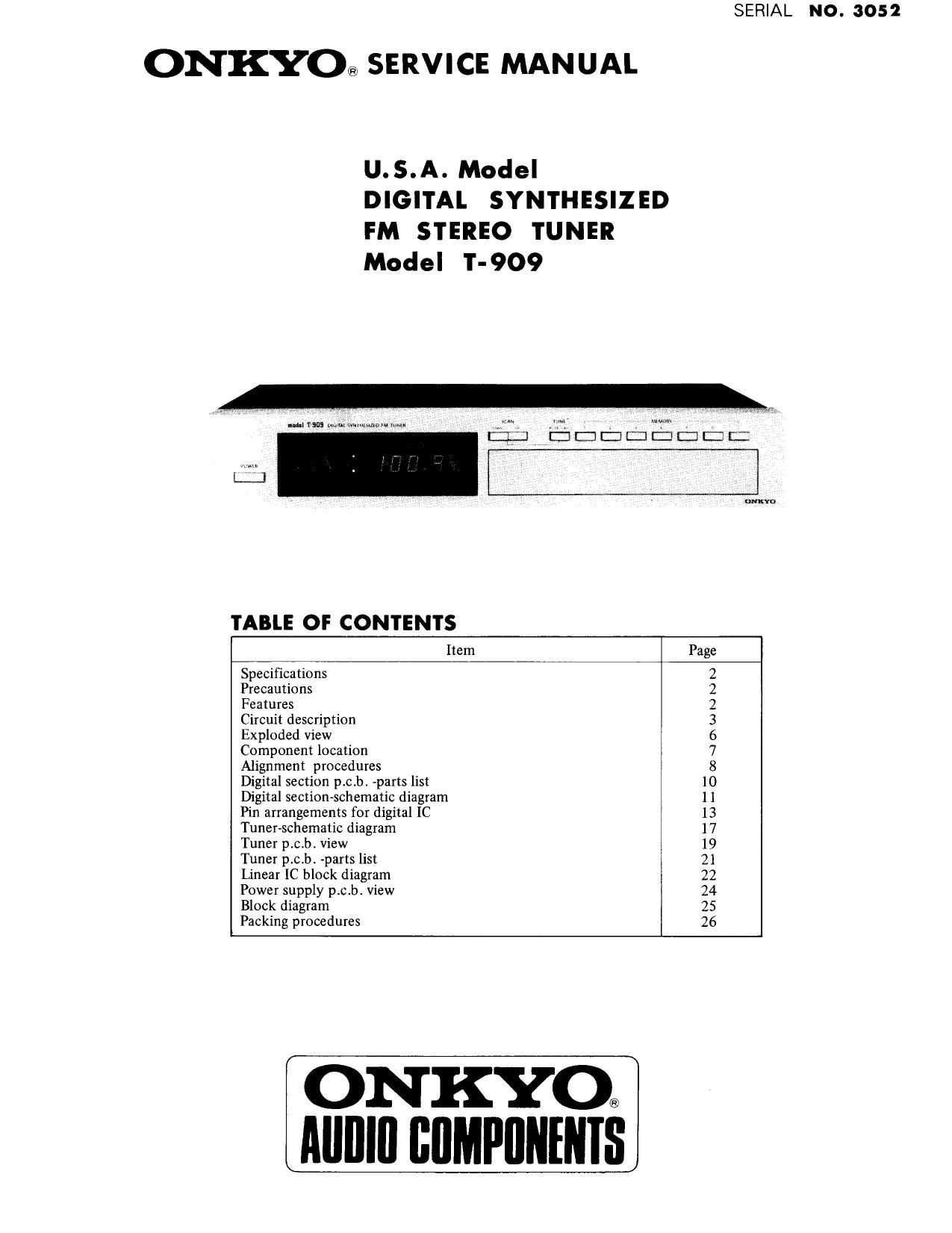
Onkyo T 909 Service Manual
This is the 19 pages manual for Onkyo T 909 Service Manual.
Read or download the pdf for free. If you want to contribute, please upload pdfs to audioservicemanuals.wetransfer.com.
Extracted text from Onkyo T 909 Service Manual (Ocr-read)
Page 1
SERIAL NO. 3052
ONKYos SERVICE MANUAL
U.S.A. Model
DIGITAL SYNTHESIZED
FM STEREO TUNER
Model T-909
TABLE OF CONTENTS
Item Page
Specifications 2
Precautions 2
Features 2
Circuit description 3
Exploded View 6
Component location 7
Alignment procedures 8
Digital section peb. parts list 10
Digital section-schematic diagram 11
Pin arrangements for digital IC 13
Tuner-schematic diagram 17
Tuner p.c.b. view 19
Tuner p.crb. -parts list 21
Linear IC block diagram 22
Power supply p.c.br View 24
Block diagram 25
Packing procedures 26
ON KYO@
Alllllll BIIMPIINENIS
Page 2
09
SPECIFICATIONS
Tuning Range: 88.l~107.9 MHz AM Suppression Ratio: 55 dB
Tuning increments: 200 kHz Harmonic Distortion: FM mono: 0.08% at 1 kHz
Usable Sensitivity: FM mono: 9.8 dBf, 1.711V IHF FM stereo: 0.15% at 1 kHz
1.3pV (S/N 26 dB, Stereo Separation: 45 dB at I kHz
40 kHz Devi.) DIN 40 dB at 100~10,000 H2
FM stereo: 17.2 dBf, 411V lHF Subcarrier Suppression: 70 dB
45uV (S/N 46 dB, Muting Level: 17.2 dBf, 411V
40 kHz Devi.) DIN Stereo Threshold: 17:2 dBf, 411V
50 dB Quieting Sensitivity: FM mono: 14.7 dBf, 3;.1V Frequency Response: 30~16,000 Hz (+0.5, -2dB)
FM stereo: 36 dBf, 35pV Tuning Frequency Accuracy: 30 ppm
Intermediate Frequency: 10.7 MHz Power Supply Rating: AC 120 volts 60 Hz
Capture Ratio: 1.5 dB Antennas: 300 ohms balanced,75 ohms
Image Rejection Ratio: 85 dB unbalanced and 75 ohms type
IF Rejection Ratio: 100 dB F connector
Spurious Rejection Ratio: 105 dB Semiconductors: 4 FETs, 56 le
Signal to Noise Ratio: FM mono: 80 dB 45 Transistors, 60 Diodes
FM stereo: 74 dB Dimensions: 450 W x 3 1/4" x 13 15/16
Alternate Channel Att.: 80 dB IHF Weight: 5.9 kg., 13.0 lbs.
Selectivity: 75 dB DIN
(:300 kHz, 40 kHz Devi.) Specifications and features are subject to change without
notice.
PRECAUTIONS
All CMOS devices have diode input protection against adverse electrical environments such as static discharge.
Unfortunately, there can be severe electrical environments during the process of handling: For example, static voltages
generated by a person walking across a common waxed floor have been measured in the 4 to 15 kV range (depending on
humidity, surface conditions, etc.). These static voltages are potentially disastrous when discharged into a CMOS input
considering the energy stored in the capacity (~300 pF) of the human body at these voltage levels.
Present CMOS gate protection. structures can generally protect against overvoltages. This is usually sufficient except in
the severe cases. Following are some suggested handling procedures for CMOS devices, many of which apply to most
semiconductor devices.
1. All MOS devices should be stored or transported in materials that are somewhat conductive. MOS devices must not be
inserted into conventional plastic snow" or plastic trays.
2. All MOS devices should be placed on a grounded bench surface and operators should ground themselves prior to
handling devices, since a worker can be statically charged with respect to the bench surface.
. Nylon clothing should not be worn while handling MOS circuits.
. When lead straightening or hand soldering is necessary, provide ground straps for the apparatus used.
. Double check test equipment setup tor proper polarity oi voltage before conducting parametric or functional testing
. All unused device inputs should be connected to VDD or VSS.
own-cu»
FEATURES
Quartz Controlled Tuning Accuracy
Onkyo has solved tuning accuracy problems once and for all by employing one of the most accurate and stable reference
frequency sources known today- the quartz crystal oscillator' 1n a quartz synthesizer tuning system. Not even the slightest
hint of station drift can be detected, irrespective of widely varying operational conditions:
Front Panel Digital Frequency Display
Befitting its high degree of tuning accuracy and stability, the T-909 displays the tuned frequency in digital form. Tuning
operations involve no more than the pushing of a few buttons - nothing could be simpler, nor any more accurate.
Frequencies may be varied one at a time in 50 kHz steps (200 kHz steps for USA) or continuously at relatively high speed.
And when the station has been accurately tuned, the TUNED indicator lamp will light up,
Tuning Memory for Automatic Tuning
A total of 7 favorite FM stations may be pre-set for automatic tuning. The actual setting operation involved is simplicity
itself, while any pre-set memory may be cleared and reset for a new station with equal ease.
High Sensitivity Plus Superb Selectivity
With dual gate MOS FETs in the front-end RF stage and mixer circuit, and a tuned buffer circuit in the local oscillator, a
truly excellent FM sensitivity of 1.7 11V (9.8 dBf) has been attained. Distant FM stations that were once too remote for
worthwhile FM listening are given greater clarity and brilliance. But what is even more remarkable is the conspicuous
absence of interference, especially from adjacent stations.
Page 17
BLOCK DIAGRAM
HA11223 (PLL FM Stereo Demodulator with Pilot Cancel)
MW -fi
Hg. a ,, ,-l
Input Pilot 4% a > m .m
Signal I A" 3,1: a j'
ltig. b . , ,, , '5 ,
Pin 9 Out 7 W
(Unused C214)
sum
Fig. c
Pin 9 Out
(Used C214)
1. Pilot Cancel Circuit Operations
The composite signal inputed from pin 2 is amplified by the Pre-Amp circuit, and then it is outputed to pin 3. This
signal is inputed to pin 12 and, one part is inputed to the PLL circuit and the other to the lamp driver circuit. The
PLL circuit locks out the pilot signal by the signal which has been inputed to the PLL circuit, and the signal in the
PLL circuit gererates three kinds of signals, 76 kHz, 38 kHz, and 19 kHz. The 19 kHz signal whose phase is advancing
90° more than the pilot signal is inputed to the Gain Control Amp.
0n the other hand, the signal inputed to the lamp driver circuit is detected synchronously by the 19 kHz signal with
the same phase as the pilot signal generated by the PLL circuit, and sent to pin 10 and pin 11 as a DC signal in pro-
portion to the level of the pilot signal.
The DC signal is amplified by DC-Amp, and used as the control signal of the above mentioned Gain Control Amp.
Therefore, when there is no load capacity C214 in the output of pin 9 that has been outputed from the Gain Control
Amp, a rectangle wave with a phase of 90° advanced as compared with the input pilot signal will appear as indicated
in the right figure b.
As a matter of fact, however, since there is C214 , a triangular wave that is in the same phase as the input pilot signal
will appear as shown in Fig. C. The level of the triangular wave correlates with the input pilot signal level and it dis-
perses due to dispersion of IC within the circuit Therefore, it is necessary to adjust properly the level by R229
(100 $28). This level adjusted triangular wave is inputed to pin 4 and is phase inverted by the transistor into 1C, then
added to the input pilot signal.
Since the pilot cancel of HA11223 is utilizing the above mentioned triangular wave injection, when the difference
between the pilot signal and the fundamental frequency component of the triangular wave is eliminated, the odd high
harmonics of the triangular wave will remain.
This high harmonic components are, needless to say, the odd times of 19 kHz, but when this signal is turned on by
switching transistors of the decoder, as the 38 kHz rectangular wave, it causes beat with the high harmonics that are
the odd times of 38 kHz, and generates a signal of 19 kHz component again.
As a result of this, the signal of 19 kHz component that appears at the output pin becomes easier to be unbalanced at
pin 5 and at pin 6 . Therefore, for the above mentioned adjustments ofR229, it becomes necessary to make each 19
kHz component appearing at pin 5 and at pin 6 the same and to maximize them.
_22,,