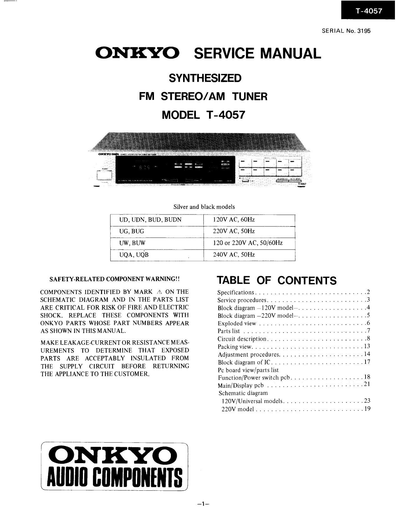
Onkyo T 4057 Service Manual
This is the 20 pages manual for Onkyo T 4057 Service Manual.
Read or download the pdf for free. If you want to contribute, please upload pdfs to audioservicemanuals.wetransfer.com.
Extracted text from Onkyo T 4057 Service Manual (Ocr-read)
Page 1
T-4057
SERIAL No. 3195
ONKYO SERVICE MANUAL
SYNTHESIZED
FM STEREO/AM TUNER
MODEL T-4057
Silver and black models
UD, UDN, BUD, BUDN 120V AC, 60Hz
UG, BUG 220V AC, 50Hz
UW, BUW 120 or 220V AC, 50/60Hz
UQA, UQB 240V AC, 50Hz
SAFETYARELATED COMPONENT WARNING
TABLE OF CONTENTS
COMPONENTS IDENTIFIED BY MARK A ON THE Specifications ............................. 2
SCHEMATIC DIAGRAM AND IN THE PARTS LIST Service procedures .......................... 3
ARE CRITICAL FOR RISK OF FIRE AND ELECTRIC Bleak diagram 7 120V modeli __________________ 4
SHOCK. REPLACE THESE COMPONENTS WITH Black diagram _220V model ,,,,,,,,,,,,,,,,,, 5
ONKYO PARTS WHOSE PART NUMBERS APPEAR Exploded View ............................ 6
AS SHOWN IN THIS MANUAL. Parts list ................................ 7
MAKE LEAKAGECURRENT 0R RESISTANCE MEAS- Cichit description .......................... 8
UREMENTS TO DETERMlNE THAT EXPOSED PaSkmg View ............................. l3
PARTS ARE ACCEPTABLY INSULATED FROM Adluitr'lem pOCfeféres """"""""""""" if:
THE SUPPLY CIRCUIT BEFORE RETURNING 11:1); 12:ng 0 l' """""""""""""
THE APPLIANCE To THE CUSTOMER. I cw/Pam. 5
Function/Power swnch pcb ................... 18
Main/Display pcb ......................... 2l
Schematic diagram
lZOV/Universal models ..................... 23
220V model ............................ l9
(ONKYO
Alllllll BflMPlINHIIs
Page 11
TC9172P (PLL IC)
T-4057
l- ________ 1
GNDE1 KiiaijD l W
Arne FM | ,
REF E 2 15 3 FM 'N FM nuts or JDO-Nl co gzouuren +- 11 $31an
- 1/16 I (Aims) nouns) mo 5"9' Pass Filter
5 l: 3 14 :lGND AMIN ' 1 I 3% Butter
M [N -~ an 10 D02
C 3
sra C 5 12 :1 TEST "0? R a" -<_l as:
0T1 C 6 11 :1 001 fianp'élfir ? s'
s. -f CK
0T2 C 7 10 :l 002 gpéqglfigL_5 S73
OUTPUT
01 I: 8 9;] 0T4 PORT
12 I '6 9-8-7-6
TEST GND Vdd LW AM MODE
FM
Pin No. Symbol Terminal Description
1 GND Ground
2 REF Reference frequency Input for reference frequency as supplied from the controller IC i.e.,
input square wave signals; 25 kHz during FM mode and 10 kHz (for 10 kHz
step range) or 9 kHz (for 9 kHz step range) during AM mode.
3 SI Serial data input This function supplies and receives data within the controller to
4 CK Serial clock input control the serial input port, determination of dividing ratio and
5 STB Strobe input versatile I/O port.
6 MODE Model output FM mode can be performed in AUTO or MONO mode by pressing
the MUTE/MODE switch on the front panel. High level at AUTO mode.
7 FM FM output High level at FM. This signal controls B circuit in AM IC, FM IF and
and multiplex circuit.
8 AM AM output High level at AM. This signal controls the B circuit in the FM in-
dicator.
9 LW Not used.
10,11 E01,E02 Error outputs Charge pump output of the phase detector which constitutes the
phase lock loop. The high level is output when the divided local
oscillator signal frequency is higher than the reference frequency from
controller. In the opposite case, the low level is output
Floating occures when the frequencies match. The output is applied
to the variable capacitor diode in the front end through the low pass
filter 0717 and 0718. The output from both terminals is same.
12 TEST
13 AM AM local oscillator AM local oscillator input
14 GND
15 FM FM local oscillator FM local oscillator input
16 VDD Power supply
_||_