Onkyo T 4017 Service Manual

This is the 22 pages manual for Onkyo T 4017 Service Manual.
Read or download the pdf for free. If you want to contribute, please upload pdfs to audioservicemanuals.wetransfer.com.

Page: 1 / 22
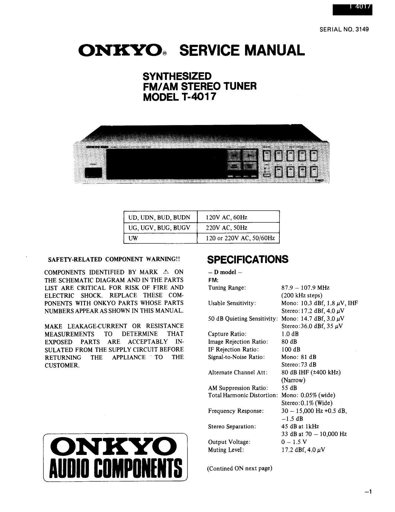
Onkyo T 4017 Service Manual

Extracted text from Onkyo T 4017 Service Manual (Ocr-read)


Page 1

ONKYO®

SYNTHESIZED
FM/AM STEREO TUNER
MODEL T-4017

SERIAL NO. 3149

SERVICE MANUAL

UD, UDN, BUD, BUDN

120V AC, 60HZ

UG, UGV, BUG, BUGV

220V AC, 50Hz

UW

120 or 220V AC, 50/60Hz

SAFETY-RELATED COMPONENT WARN INGII

COMPONENTS IDENTIFIED BY MARK A ON
THE SCHEMATIC DIAGRAM AND IN THE PARTS
LIST ARE CRITICAL FOR RISK OF FIRE AND
ELECTRIC SHOCK. REPLACE THESE COM-
PONENTS WITH ONKYO PARTS WHOSE PARTS
NUMBERS APPEAR AS SHOWN IN THIS MANUAL

MAKE LEAKAGE-CURRENT OR RESISTANCE
MEASUREMENTS TO DETERMINE THAT
EXPOSED PARTS ARE ACCEPTABLY IN-
SULATED FROM THE SUPPLY CIRCUIT BEFORE
RETURNING THE APPLIANCE TO THE
CUSTOMER.

ONKYO
Alllllll IIIIMPIIIIIIIIS

SPECIFICATIONS

- D model -

FM:

Tuning Range: 879 - 107.9 MHZ

Usable Sensitivity:

50 dB Quieting Sensitivity:
Capture Ratio:

Image Rejection Ratio:

IF Rejection Ratio:
Signal-to-Noise Ratio:

Alternate Channel Att:

AM Suppression Ratio:
Total Harmonic Distortion:

Frequency Response:
Stereo Separation:

Output Voltage:
Muting Level:

(Confined ON next page)

(200 kHz steps)

Mono: 10.3 dBf, 1.8 11V, [HF
Stereo: 17.2 dBf, 4.0 uV
Mono: 14.7 dBf, 3.0 1.1V
Stereo:36.0 dBf, 35 1.1V
1.0 dB

80 dB

100 dB

Mono: 81 dB

Stereoz73 dB

80 dB 1HF(1400 kHz)
(Narrow)

55 dB

Mono: 0.05% (wide)
Stereo:0.1% (Wide)

30 - 15,000 Hz +0.5 dB,
--1.5 dB

45 dB at 1kHz

33 dB at 70 - 10,000 Hz
0 # 1.5 V

17.2 dBf,4.0 uV

Page 2

1 4017

AM:

Tuning Range: 530 f 1620 kHz
(10 kHz steps)

Usable Sensitivity: 25 [4V

Image Rejection Ratio: 40 dB

IF Rejection Ratio: 40 dB

Signal-to-Noise Ratio: 40 dB

Total Harmonic Distortion: 0.7 %

Output Voltage: 0 - 500 mV
General
Antennas: FM: 300 ohms balanced and
75 ohms unbalanced
AM: Built-in loop antenna
and external terminal
Semiconductors: FETs: 4 TR: 59 le: 16
Diodes: 72 LEDs: 25 '
Dimensions: 43 5(W) x 77(H) x 373(0) mm
(17-1/8" x 3" x 14-3/4")
Weight: 4.8 kg., 10.6 lbs.
- G/W models -
FM:

87.5 - 108.0 MHz

(50 kHz steps)

Mono: 10.3 dBf, 1.8 uV, IHF
Stereo: 17.2 dBf, 4.0 p.V
Mono: 14.7 dBf, 3.0 pV
Stereo:36.0 dBf, 35 11V

Tuning Range:
Usable Sensitivity:

50 dB Quieting Sensitivity:

Capture Ratio: 1.0 dB
Image Rejection Ratio: 100 dB
1F Rejection Ratio: 100 dB
Signal-to-Noise Ratio: Mono: 81 dB

Stereo:73 dB

TABLE OF CONTENTS

Specifications ............................ 1

Service procedures ......................... 3

Circuit description ......................... 4
Synthesizer and controller description .......... 4
Diode and key matrix connection ............. 6
Indicator circuit ......................... 7
AGC circuit ............................ 7
Auto high blend circuit .................... 7
Muting circuit .......................... 8
IF band width switching circuit ............... 9
Station detection circuit .................. 10
FM/AM switching circuit .................. 10
PLL tuned circuit ....................... 11

Linear IC block diagram ..................... 12

Selectivity: 70 dB DIN (1300 kHz, 40 kHz
dev.) (Narrow)
AM Suppression Ratio: 55 dB

Total Harmonic Distortion: Mono: 0.05% (Wide)
Stereo:0.l% (Wide)

30 - 15,000 HZ +0.5 dB,
71.5 dB

45 dB at 1 kHz

33 dB at 70 - 10,000 Hz
0 - 1.5 V

Frequency Response:
Stereo Separation:

Ontput Voltage:

Muting Level: 17.2 dBf, 4.0 11V

AM:

Tuning Range: 522 7 1611 kHz (9 kHz steps)
Usable Sensitivity: 25 uV

Image Rejection Ratio: 40 dB

IF Rejection Ratio: 40 dB

Signal-to-Noise Ratio: 40 dB

Total Harmonic Distortion: 0.7 %

Output Voltage: 0 -- 500 mV
General
Antennas: AM: 300 ohms balanced and
75 ohms unbalanced
AM: Built-in loop antenna :
and external terminal
Semiconductors: FETs: 6 TR: 59 ICs: 16
Diodes: 72 LEDs: 25
Dimensions: 435(W) x 77(H) x 373(D) mm
(17-1/8" x 3" x 14-3/4")
Weight: 4.8 kg., 10.6 lbs.

Specifications and features are subject to change without
notice.

Packing view ............................ l3
Exploded view ........................... 14
Parts list ............................... 15
Adjustment procedures ..................... 16
Block diagram - 120V model - (W mode) ........ 19
Block diagram - 220V model - ............... 20
Schematic diagram - 120/ 220V model - ......... 21
PC board view from component side

Controller, display and switch section .......... 23
Printed circuit board-parts list ................. 23
Schematic diagram -220V model - ............. 25
Pc board view from component side ............. 27
Schematic diagram - 120V model - ............ 29
Printed circuit boardrparts list ................. 31