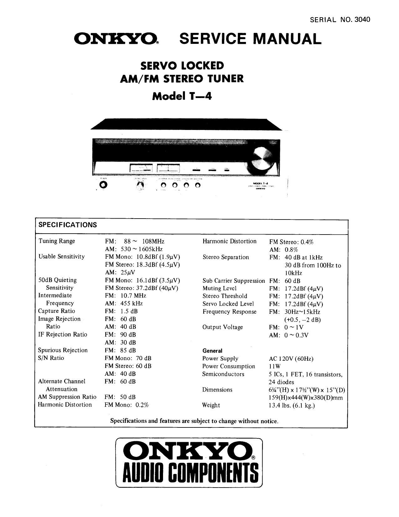
Onkyo T 4 Service Manual
This is the 9 pages manual for Onkyo T 4 Service Manual.
Read or download the pdf for free. If you want to contribute, please upload pdfs to audioservicemanuals.wetransfer.com.
Extracted text from Onkyo T 4 Service Manual (Ocr-read)
Page 2
BLOCK DIAGRAM
m cum
ANYENNA
xvm aim mi a va
P803
swENem
METER
sweep
mom/non
s
IF FILYER IF AMP [F FIUER
YERMINAL am
communes
020 OUTPUT
DEYECTOR
MFX FtL Ic 5
LEVEL
0 ..
Hm...
rm
m 2 Its {a 0
m ,4. H; .
Hi WSE J. J, m cm R23.
w
ms
MUTELEVEt Vco SE?
ADJUSV Amusr ADJUST
on: my}
osc Rm
srrwo
LOCKED
ADAUSY
5mm"
'RlGGER
mm SE wsne
AM P
[OCKED
LAMP
SWI m4
LOCKED
LAMP
tram
RECVIFlER
Automatic Servo Locked Tuning System
The outstanding feature of this high quality stereo tuner
is the Servo Locked Tuning System, FM stations are tuned
immediately, automatically, and accurately, without the
slightest fine tuning adjustment required at all. Simply
tune approximately to the desired FM station, and then let
go. The automatic servo locked tuning circuit does the rest,
fine tuning the station with uncanny electronic precision.
The station remains firmly locked for as long as you
want without the slightest hint of station drift - a great
advantage during important recording sessions.
Human Touch Sensor" Tuning Knob
An essential part of the Servo Locked Tuning System is
the tuning knob itself, connected to a special sensor circuit.
When your hand touches the tuning knob to tune to the
desired station, the servo locked tuning circuit is temporari-
ly disconnected". But when you let go of the tuning knob,
after tuning approximately to the FM station, the servo
locked tuning circuit is reactivated via the special sensor
circuit, locking the station to dead center tuning. No fine
tuning adjustments are required since the servo lock system
automatically compensates for tuning differences.
FET Front End
High sensitivity matched by minimal intermodulation distor-
tion has been achieved by equipping the front end with a
high grade FET (field-effect transistor).
Phase Locked Loop Stereo Decoder IC
The broadcasting station pilot signal plus a switching signal
generated in the MPX (stereo decoder) circuit, are locked in
a PLL circuit (enclosed in a specially designed IC) thereby
ensuring excellent stereo separation, and a very low distor-
tion level. This 1C also features better frequency response
and low carrier leak.
Epoxy PC Board FM Oscillator Circuitry
All FM oscillator.elements are on epoxy PC board to ensure
drift-free stability in oscillator frequency despite changes in
temperature and humidity.
De-Emphasis Switch
De-emphasis is normally set to NORMAL (75 usec), but for
reception of FM Dolby broadcasts switch to the 25 usec
position.