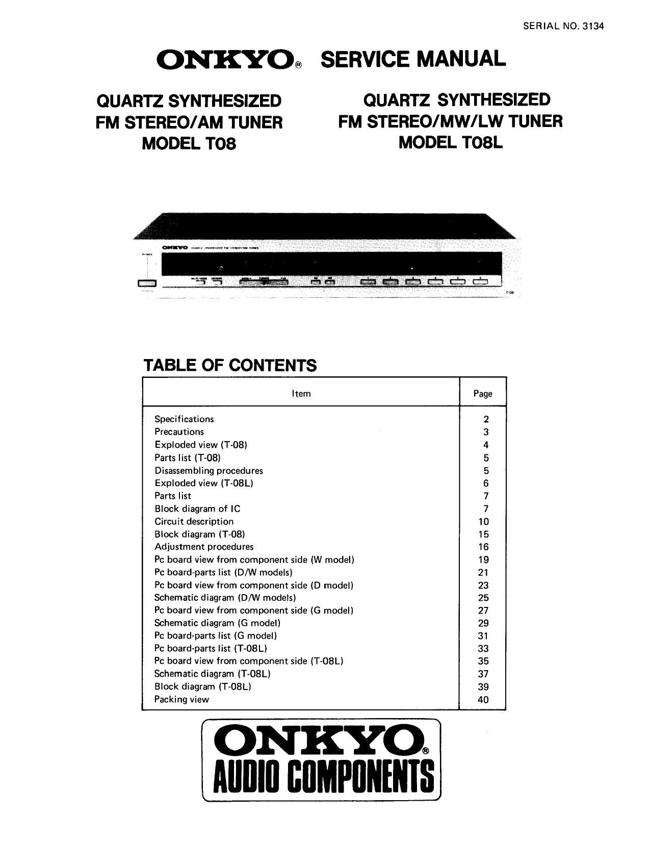
Onkyo T 08 L Service Manual
This is the 27 pages manual for Onkyo T 08 L Service Manual.
Read or download the pdf for free. If you want to contribute, please upload pdfs to audioservicemanuals.wetransfer.com.
Extracted text from Onkyo T 08 L Service Manual (Ocr-read)
Page 1
SERIAL N0. 3134
ONKYO® SERVICE MANUAL
QUARTZ SYNTHESIZED QUARTZ SYNTHESIZED
FM STEREO/AM TUNER FM STEREO/MW/LW TUNER
MODEL T08 MODEL T08L
TABLE OF CONTENTS
Item Page
Specifications 2
Precautions 3
Exploded view (Tv08) 4
Paris list (T-08) 5
Disassembling procedures 5
Exploded view (T~08L) 6
Parts list 7
Block diagram of IC 7
Circuit description 10
Block diagram (T-OB) 15
Adjustment procedures 16
Pc board view from component side (W model) 19
Pc board-parts list (D/W models) 21
Pc board view from component side (D model) 23
Schematic diagram (D/W models) 25
Pc board view from component side (G model) 27
Schematic diagram (G model) 29
Pc board-parts list (G model) 31
Pc board-parts list (T-08L) 33
Pc board view from component side (T-08L) 35
Schematic diagram (T-OSL) 37
Block diagram (T-08Ll 39
Packing view 40
ON KYOQ
Alllllll llllMl'llllllllS
Page 11
2. Control Key Connections __
UP, DOWN ..... Pressing the UP or DOWN key will cause D424
the frequency to be shifted upward or downward (in 32 fl .> 3 .3
200kHz steps with the D model and in 50 kHz steps with the EN x EN 6\
W/G model). If the key is pressed for more than 0.5 D423 n, m w A1 M N W N
seconds, the frequency will be shifted 50 kHz every 40ms 2 Era-if f '5
until it is released. D 422 B\ A b\/\ }\
MW, FM, LW ..... The MW,FM, LW band switches. K. :1 Menonvi m N "a m N
MEMORY ..... Pressing this key causes the memory to be f 3 >
placed in the write-enabled state. The frequency displayed D421 6\ RN \ b\/\
will be stored in one of the memories 1-6 if the correspon- no E g 1: m "7) Wm
ding memory key is then pressed within 5 seconds. The A
write-enabled state will be cleared after 5 seconds if none of \ N
DOWN M5
the memory keys are pressed, or if the AM/FM selector A K K K
keys are pressed. (X): NOT USED D433 D419 D418 D417
Ml-M7(M6) ..... These keys are used to preset and recall LW: T'OBL , ,0 19 n
the contents of the memory. Positions are provided for So 5,, 5: 5d
keys for reading/ writing up to 7 frequencies, but only 6 Fig. 2
keys are installed in the T-08. See the paragraph on
MEMORY for writing frequencies. Pressing one of the
keys M1-M6 once will cause the contents of the corresponding memory (a frequency) to be read. A muting signal of about 0.45
seconds duration is output at this time.
TPP (Tracking Point Preset) ..... Switch is used to write adjustment frequencies into preset memory during set production. Not
used with the T08. When the IC VDD is first inserted, the lowest FM and MW frequency is placed in the memory.
3. Key Matrix Connections
lnput
T 1
7\ 0mm" mm KO (25) K1 (24) K2 (23) K3 (22)
1 W Terminal
3 sr (l6) 9kHz/10kHz AUTO/MANU
Sg (15) BAND 0 BAND 1 IF 1 IF 0
04% 0:15 'l """" 0 used table 1
220V (G model) 16 15 High level when the diode is connected
D415 and D416 are not used for 120V model.
Fig. 3 5' 5g [F 1 IF 0 IF Frequency
0 0 l0.700MHz
lFl, lFO ..... lF offset value settings for FM. See Table 2. 0 1 10.67SMHZ
$331133]: BANDO ...... Geographical FM band settings. See 1 0 10.750MHz
9kHz, lOkHz ..... MW band settings. See Table 4. 1 1 10.725Ml-lz
AUTO/MANUAL ..... Auto tuning for 1, manual tuning table 2
for 0. Manual only with the T-08.
BAND 1 BAND 0 Band Frequency Range Channel Space
0 0 120V model 87.9V107.9MHZ 200kl-lz
0 1 220V model 87.50V108.00MHZ SOkHz
l 0 Japan 76,1V89.9MHZ lOOkHz
table 3
Channel Reference
9kHz/10kl-lz Frequency range Space Frequency
0 S30V1620kl-lz lOkl-Iz IOkHz
l SZZVlollkHz 9kHz 9kHz
table 4
-11,