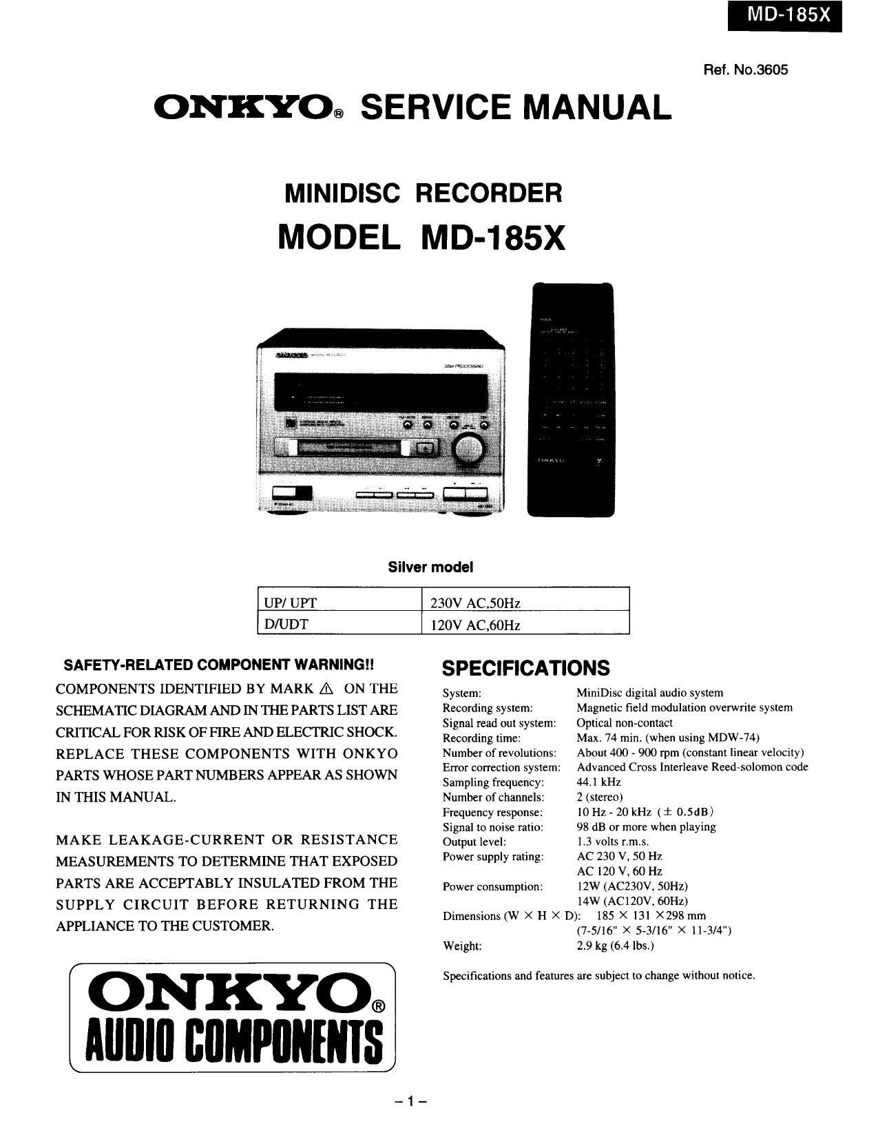
Onkyo MD 185 X Service Manual
This is the 32 pages manual for Onkyo MD 185 X Service Manual.
Read or download the pdf for free. If you want to contribute, please upload pdfs to audioservicemanuals.wetransfer.com.
Extracted text from Onkyo MD 185 X Service Manual (Ocr-read)
Page 1
Ref. No.3605
ONKYO® SERVICE MANUAL
MODEL MD-185X
Silver model
UP/ UPT 230V AC.50HZ
D/UDT 120V AC,60HZ
SAFETY-RELATED COMPONENT WARNING SPECIFICATIONS
COMPONENTS IDENTIFIED BY MARK A ON THE System: MiniDisc digital audio system
SCHEMA'HC DIAGRAM AND IN THE PARTS LIST ARE Recording system: Magnetic field modulation overwrite system
Signal read out system: Optical noncontact
CRITICAL FOR RISK OF FIRE AN D ELECTRIC SHOCK Recording time: Max. 74 min: (when using MDW~74)
REPLACE THESE COMPONENTS WITH ONKYO Number of revolutions: About 400 - 900 rpm (constant linear velocity)
PARTS WHOSE PART NUMBERS APPEAR AS SHOWN gang; $322216 Ziitem: xix? Cross Inlerleave Reed-solomon code
IN THIS MANUAL. Number of channels: 2 (stereol
Frequency response: l0 Hz - 20 kHz (i 0.5dB)
Signal to noise ratio: 98 dB or more when playing
MAKE LEAKAGE-CURRENT OR RESISTANCE Output level: L3 volts n.5,
MEASUREMENTS TO DETERMINE THAT EXPOSED Power supply Ming: 2% 38 I :3 :2
, z
PARTS ARE ACCEPTABLY INSULATED FROM THE power consumption: 12W (ACZSOV, 50Hz)
SUPPLY CIRCUIT BEFORE RETURNING THE D' . (W X H X D)Mwli§15xc><121(;\l]:02§;)
ImfiflSIOHS 2 mm
APPLIANCE TOTHECUSTOMER. (7»5/l6" X 5-3/16 X 1173/ u)
Weight: 29 kg (64 lbs,)
ONKYO Specifications and features are subject to change without notice.
®
Page 2
SERVICE SAFETY PRECAUTIONS
1. Heplaclng the fuses
_' _ This symbol located near the fuse
indicates that the fuse used is fast
operating type. For continued protection against fire
hazard. replace with same type fuse. Forfuse rating
refer to the marking adjacent to the symbol.
_I:I:I_ Ce symbole indique que la fusible
utilise est a rapide.
Pour une protection permanents, n'utiliser que des
tusibles de meme type.
Ce darnter est tndlque Ia qu Ie present symbol est
appose.
CIRCUIT N0. PART NO. DESCRIPTION
F901 252075 2.5A-SE-EAK,Primary
NOTE:
23OV model only
TABLE OF OCNTENTS
Specifications 1
Service safety precautions 2
Caution on replacement of optional pickup 2
Protection of eyes from laser beam during servicing 3
Laser warning label 3
Chassis exploded view 4
Chassis exploded view parts list 5
MD mechanism exploded view 6
MD mechanism exploded view parts list 7
Block diagram 8
Microprocessor terminal descriptions 9
IC block diagrams and descriptions 11
MD mechanism replacing 23
MD mechanism disassembly 29
MD mechanism section 30
Message list 32
Printed circuit board view from bottom side 33
Schematic diagram 35
Printed circuit board parts list 37
Packing view/parts list 39
CAUTION ON REPLACEMENT OF OPTIONAL PICKUP
The laser diode in the optical pickup block is sensitive to
static electricity, surge current and etc. The components
are liable to be damaged or its reliability remarkably
deteriorated.
PRECAUTIONS
During rcpair,carcfully take the following precautions,
(The following precautions are included in the service
parts.)
LGround for the work-desk.
Place a conductive sheet such as a sheet of copper
(with impedance lower than 10Mohm) on the work-
dcsk and place the set on the conductive sheet so that
the chassis can be grounded.
2.Grounding for the test equipments and tools.
Test equipments and toolings should be grounded in
order that their ground level is the same the ground of
the power source.
3. Grounding for the human body.
Be sure to put on a wrist-strap that is properly
grounded.
Be particularly careful when wearing synthetic fiber
clothes. or air is dry.
4. Select a soldering iron that permits no leakage and
have the tip of the iron well-grounded.
5. Do not check the laser diode terminals with the probe
of a circuit tester or oscilloscope.
Page 4
CHASSIS EXPLODED VIEW
Page 24
24. Check after the replacement
After the replacement, confirm that the following points are within the specifications.
1) 1). Write of EEPROM
a).Short between pin 2 and pin 8 of IC402 on the MD mechanism PC board. Attach the mechanism on the unit.
b).Set the unit to "TEST MODE". (Refer to "How to set test mode " on page 26. (EJECI' is displayed)
c).lnsert the recordable reference disc (TEAC MMD-317 corresponding).
d).As AUTO YOBl is displayed, push PLAY/PAUSE key to enter the automatic mode.
e).Afler COMPLETE is displayed, push STOP key.(The inditztor is not constant.)
f).After wait for approx. 3 seconds, turn the STANDBY key to OFF.
g).After wait for approx. 3 seconds, push the ENTER key of the remote control.
h).Press EIECF key to take off the disc.
When the disc is not ejected, perform from step b).
i) Disconnect the shorted circuit between pins 2 and 8 of [0102 on the mechanism PC board and
attach the mechanism assembly on the unit.
2). Error rate measured by Pre-rnastered Disc must be within the specification.
3). Error rate measured by Recordable Disc must be within the specification.
4). Error rate at self recordinyplayback must be within the specification.
5). Measurements for the location of lead-in switch must be within the specification. If not, adjust it
referring to Fig. 2-2.
6). Confirm the Grating is within the specification.
MECHA SWITCH PCB
3. MD Mecha PCB replacement
3-1. Check after the replacement
Compatibility with pickup is changed after replacement 5:35:22;
of MD mechanism PCB.
Please rewrite EEPROM. refer to the item 24(1).
MAGNETIC
4. Ma etic head re lacement
gn P HEAD
4-1. Replacement process
1). Pull out the red color socket( CN 1604) of slide motor MD-MECHA
and head(CN1252), add 5 volts at the socket(CN1604)
to move the pick up to the outermost position.
2). Pull out the socket of magnetic head, unscrew
and replace the head. (refer to Fig. 2-3)
3). Insert the sockets of magnetic head and slide motor.
4-2. Check after the replacement
Make recording and measure the error rate by using the recorded disc.
Error rate must be within the specification.
(Note). Refer to separate document (MD-185x MD mechanism measurements methods)
for the measurement methods and the specifications.
_ 24 _
Page 25
5. Replace the spindle motor
When a motor get old, metalic dust will adhere around the brush
and it will decrease the impedance by
causing a shot circuit on the coil. 'lhis will result an insufficient
capability of the driving circuitry andunstable rotating.
To deter: this, connect a digital multi meter (Circuit Tester is not good)
to the moter and rotate the meter may cause skipping etc.
slowly by hand. If the resistance decreases at patlcular point,
the motor is defective. Defective motormay cause skipping sound, etc..
5-1. Procedure to replace the spindle motor
1). Disconnect four sockets (white x2, red and blue) and CN1601
(FFC 5 leads) on the PCB.
2). Unscrew the four screws which fix the PCB. Raise the PCB
from the right side affront view,leaving the left side
(pick up FFC side) in place. Unlock the CNllOl socket
and pull out the FFC.
3). Unscrew the three screws that fix the spindle motor
and replace the motor. Fasten the screw temporarily for alignment.
5-2. Alignment alter the replacement
1). Use an extension 116 and connect it as shown in Fig. 4-2.
2) Connect an oscilloscope to the test points of the PCB as shown in
Fig. 4-3. (Refer to Fig. 4-4 for the wirings.) (on page 28)
3). Adjust the position of spindle motor while observing the lissajous' \ ..
figure,by using a screw driverput into the hole for adjustment. 9 ADJUSTMENT POINT
(Refer to Fig. 44)
2P EXTENSION CONNECTOR
From HEAD
5p EXTENSION FFC [-r-fl (Fig 4- 1 )
L_]|:II:Jl:l :1
From (m
MOTER Extension substrate used for service.
MAIN PC BOARD (OP 36)
>WlTGH PC
' From PlCKrUP
: CNP1061
.
CNP1602
cmmeos
- CNP1 101
_: CNP1064
6P- 2P EXTENSION CONNECTOR
_
TP-1133
TP-1132
(Fig 4-3)
- 25 - GND