Onkyo M 502 Schematic

This is the 12 pages manual for Onkyo M 502 Schematic.
Read or download the pdf for free. If you want to contribute, please upload pdfs to audioservicemanuals.wetransfer.com.

Page: 1 / 12
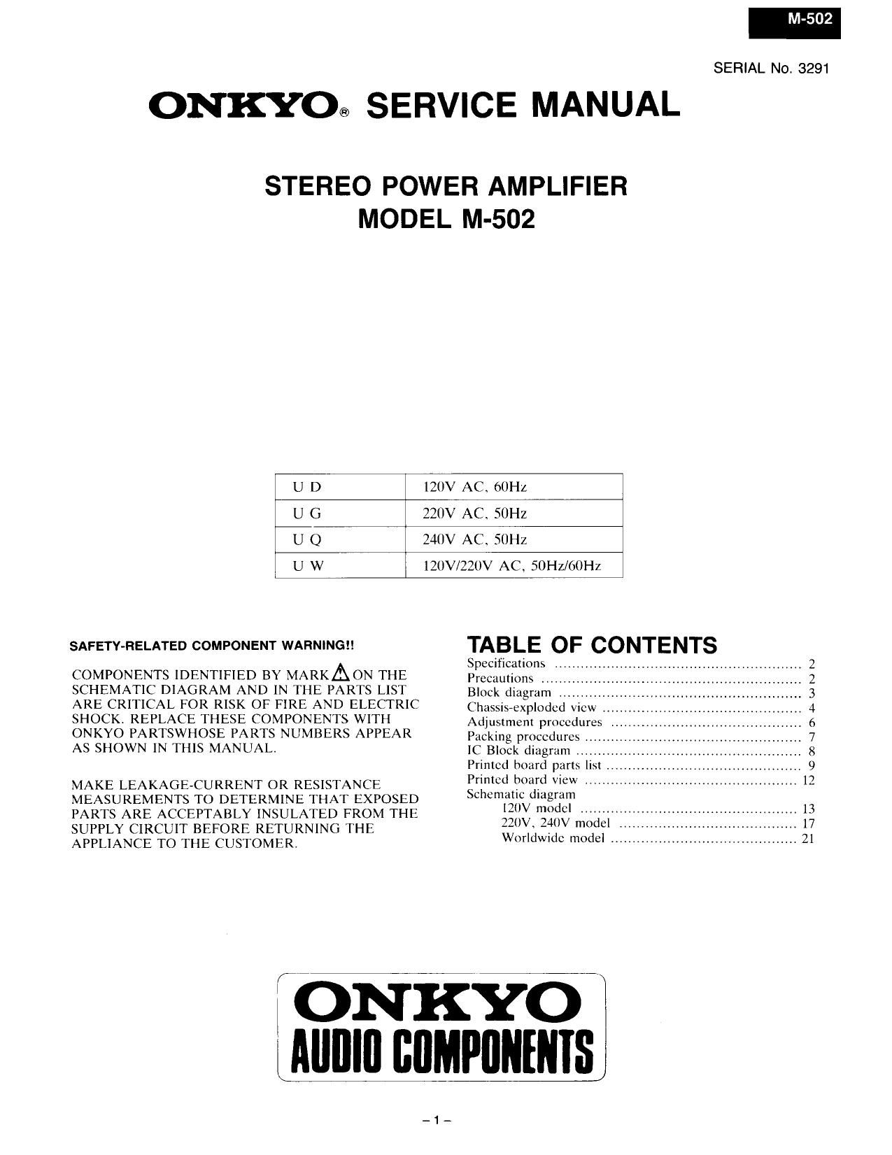
Onkyo M 502 Schematic

Extracted text from Onkyo M 502 Schematic (Ocr-read)


Page 1

M-502

SERIAL No. 3291

ONKYO® SERVICE MANUAL

STEREO POWER AMPLIFIER
MODEL M-502

UD

120V ACV filIHz

UG

220V AC, SOHZ

UQ

240V AC. SUIIZ

IZUV/ZZUV AC, 50Hz/60Hz

SAFETWRELATED COMPONENT WARNINGI!

COMPONENTS IDENTIFIED BY MARKAON THE
SCHEMATIC DIAGRAM AND IN THE PARTS LIST
ARE CRITICAL FOR RISK OF FIRE AND ELECTRIC
SHOCK REPLACE THESE COMPONENTS WlTI'I
ONKYO PARTSWHOSE PARTS NUMBERS APPEAR
AS SHOWN IN THIS MANUAL.

MAKE LEAKAGE-CU RRENT OR RESISTANCE
MEASUREMENTS TO DETERMINE THAT EXPOSED
PARTS ARE ACCEPTABLY INSULATED FROM THE
SUPPLY CIRCUIT BEFORE RETURNING THE
APPLIANCE TO THE CUSTOMER.

TABLE OF CONTENTS

Specifications
Precautions
Block diagram ..
Chassis-exploded vlcw
Adjustment procedures .
Packing procedures H
[C Block diagram .
Printed board parts Ii
Printed board view
Schematic diagram

IZIIV modcl

220V 240V model . ,,

Worldwide model ........................................... 21

Page 2

SPECIFICATIONS

2X220 watts at 4 ohms,

lkHz (DIN)

2Xl45 watts at 8 ohms,

lkHz (DIN)

140 watts per channel, min.
RMS, at 8 ohms, both
channels driven. from 2()Hz
to 20kHz. with no more

than 0.005% Total

Harmonic Distortion

ZX4ZS watts at 2 ohms. tkHz
2x290 watts at 4 ohms, lkI-Iz
0.005% at rated power
(100.5% at 1 watt output
(1.004% at rated power
(1.004% at 1 watt output

+0. -l.5dB at lHl to

Continuous Power:

Output:

Dynamic Power Output:
Total Harmonic Distortion:
Intermodulation Distortion:

Frequency Response:

lOOkHz
Input Sensitivity: 1.0V
Input Impedance: 20 kohms

Damping Factor: 140 (8 ohms, lkI-Iz)

S/N ratio: lZUdB (IHF»A, Shorted)
Outputs: SPEAKERS l & 2
AC OUTLET (120V models
only)
Inputs: INPUT

PRECAUTIONS

t. Replacing the fuses
For continued protection against risk fire. replace only with
same type and same rating fuse.

CIRCUIT NO. PART NO. DESCRIPTION

F801.F802 252050 5A (ST-6), Primary fuse
(IZUV:12(lV/22UV model)

FXUIfXOZ 252075 2.5ArSEeEAK, Primary fuse
(220V model)

F803,F804 252075 2.5A-SE-EAK. Primary fuse

(HOV/220V model)

2. Replacing the lamp
This unit uses the lamp listed below.

PART NO.
210160

DESCRIPTION
PLl4V150mA

CIRCUIT NO.
PL701. PL7U2

3. Insulation resistance mesurement (Only U.S.A. model)
Connect the insulatingvresistance tester between the plug of
power supply cable and the terminal GND on the back panel.
Specifications; More than 10 MD at 500V.

Power Supply: European models:
AC 220V. 50Hz
Canadian models:
AC 120, 60Hz
U.K. & Australian models:
AC 240V, SUI-[z
Worldwide models:
AC 120V and 220V
switchable, 50/60Hz
435x186x423 mm
l7-l/8X7-5/l6"><16-5/8
465x187><423 mm
18-5/16"x 7-3/8X16-5/8"
18.5 kg (40.8 lbs.)
200 kg (44.1 lbs.)

Dimensions (WXH X D):
Wide side panels (WX H X D):

Weight:
With side panels:

Specifications and features are subject to change
without notice.

4. Voltage selector (rear panel)

Worldwide models are equipped with a voltage selector to
conform with local power supplies. Be sure to set this switch
to match the voltage of the power supply in your area before
turning the power switch on: Voltage is changed by sliding
the groove in the switch with a screwdriver to the right or
left. Confirm that the switch has been moved all the way to
the right or left before turning the power switch on. Models
without a voltage selector can only be used in areas where
the power supply is the same as that of the unit.

EEC! CID

V .- .__+
220V~ 120V~ 220V~ 120V~
at ACZZOV at AClZOV