Onkyo HTR 993 Service Manual
This is the 108 pages manual for Onkyo HTR 993 Service Manual.
Read or download the pdf for free. If you want to contribute, please upload pdfs to audioservicemanuals.wetransfer.com.
Extracted text from Onkyo HTR 993 Service Manual (Ocr-read)
Page 1
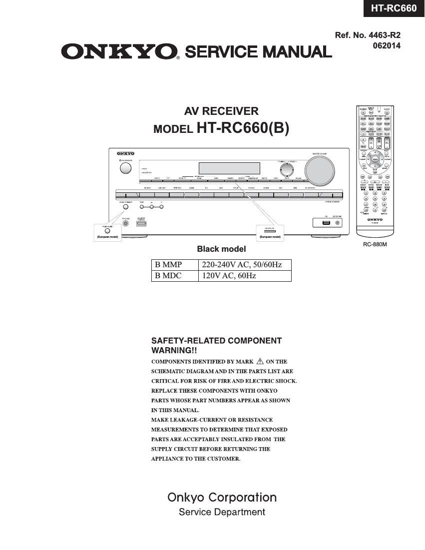
HT-RC660
Ref. No. 4463-R2
ONKYO® SERVICE MANUAL 2°
AV RECEIVER
MODEL HT-RC660(B)
{imp-an mom!)
RC»880M
Black model
B MMP 220-240V AC, 50/60Hz
B MDC 120V AC, 60Hz
SAFETY-RELATED COMPONENT
WA R N I N G ! !
COMPONENTS IDENTIFIED BY MARK A ON THE
SCHEMATIC DIAGRAM AND IN THE PARTS LIST ARE
CRITICAL FOR RISK OF FIRE AND ELECTRIC SHOCK.
REPLACE THESE COMPONENTS WITH ONKYO
PARTS WHOSE PART NUMBERS APPEAR AS SHOWN
IN THIS MANUAL.
MAKE LEAKAGE-CURRENT OR RESISTANCE
MEASUREMENTS TO DETERMINE THAT EXPOSED
PARTS ARE ACCEPTABLY INSULATED FROM THE
SUPPLY CIRCUIT BEFORE RETURNING THE
APPLIANCE TO THE CUSTOMER.
Onkyo Corporation
Service Department
Page 2
TX-NR535/636/737/838/DTR-30.6/40.6/50.6/HT-R593/693/993/HT-RC660
DEBUG MODE-1
AUDIO DEBUG MODE-1/5
The operations of DSP and DIR etc are able to checked by the information displayed on FL in this debug mode.
This information will help to analysing digital audio no sound trouble,
To set in Debug mode
1. Press twice the ON/ STANDBY key while pressing the DISPLAY key.
e-Q- 7 The version number of Microprocessor is displayed
M1'03/14307ALN only for 3 seconds
2 Press + (TONE) button while the version number of microprocessor is displayed.
e.g. N1.02/14210ALA _ ESE/\f/grrsgiosggglerZer of DSP Is displayed
3. Press DISPLAY button while the version number of DSP is displayed.
89 0A0002: :00 Step4
4. Proceed to the next step by pressing the DISPLAY key.
ANA .'o:NON:C: Step-2
4v
1:ANA 048k048k Step-3
4v
AUDIO dubug mode
2/0. 01 2. 053/4 Step-4 The status of DSP and DIR etc
4' will be displayed.
2:0:PCM :PCM Step-5
4v
00:X:F.'OFF Step-6
4v
SPO0F*00F00409 Step-7
4v
48 482568 TB Step-8 i
4v
L :0000 0000
vi
SW :0000 0000
4v
Exit
Page 14
838/ HT-RC6 HT-R993/ TR-
OPERATION CHECK-3
CONFIRMATION OF VOLTAGE-DETECTION PROTECTORS.
Don't connect load nor short speaker terminals.
1. Do the lollowing operation.
1-1. set the volume level to 25(TX-NR636, DTR-30.6) or 30(TX-NR737, 838, DTFl-40, 50.5).
1-2. [TV/CD] + [ON/STANDBY] 4» [BD/DVD]
1-3. from; +]
to the following test mode.
TEST 1-01
2. AVFt automatically tests in the following test sequence. And if it is all OK, Wi-Fi test will begin.
Test sequence
(FL+) a (FR-) ~> (0+) a (SL-) 4» (SR+) a (SBL-) 4» (SBR+)
3. If FL tube displays Wi-Fi check mode then voltage-detection protectors test will be completed.
CONFIRMATION OF UPDATE ROUTE.
1. Do the following operation.
1-1. set the Volume level to 25(TX-NR636, DTR-30.6) or 30(TX-NR737, 838, DTFl-40, 50.5).
1-2. [TV/CD] + [ON/STANDBY] a [BD/DVD]
1-3. new; +1
to the following test mode.
TEST 1-01
2. Once the above mentioned test mode is entered, voltage-detection protectors function is checked automatically first, then update
route check will begin.
If the result of update route check is no problem then Wi-Fi check will begin. If the result is NG then NG message will be shown on
the FL tube.
3. If FL tube displays Wi-Fi check mode then voltage-detection protectors test and update route check are passed.
Detail of NG number of F/W update route test is as below.
2 VI . OSD OSD is except TX-NFl636 and DTR-30.6
3 DASSO . KGZH
4 VI . HDCP TX
CONFIRMATION OF Wi-Fi CONNECTION
1. Setting Wi-Fi routers.
2. set the following test mode.
TES T 1-01
3. Once the above mentioned test mode is entered, voltage-detection protectors function is checked automatically first, then update
route check will begin and then Wi-Fi check will begin.
In Wi-Fi check mode, it connects an access point automatically. Wi-Fi LED flashes during connection.
4. If connection is completed and IP address is successfully acquired, Wi-Fi LED turning lights off and the value of FlSSI to an access
point is displayed in dBm.
If the connection is failed, NG is displayed.
9-9 02 -55d 0114
Qim
SSID No RSSl(dbm) Time Counter
In case value of RSSI level Isn't showed on the FL tube at all past 4 minutes in this timer mode, judge as NG.
The sound from USB flash device is output from Zone2 PREOUT or Zone2 LINEOUT via Zone2 DAC.
CONFIRMATION OF ZONE2 DAC ROUTE
1. Connect USB memory or USB storage to AVFl front USB port.
2. set the following test mode.
TEST 1-01
3. After being displayed Wi-Fi RSSI level, it will play back wave file from USB storage.
4. Check the wave lorm that appears L+R and Ft alternately from the following output terminal.
Output terminal : ZONE2 LINE OUT
Wi-Fi LED is turn on in Zone2 DAC check mode.