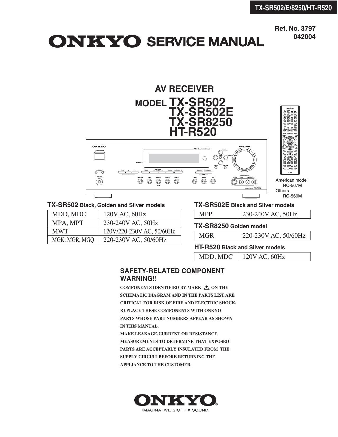
Onkyo HTR 520 Service Manual
This is the 117 pages manual for Onkyo HTR 520 Service Manual.
Read or download the pdf for free. If you want to contribute, please upload pdfs to audioservicemanuals.wetransfer.com.
Extracted text from Onkyo HTR 520 Service Manual (Ocr-read)
Page 1
TX-SRSOZ/E/8250/HT-R520
Ref. No. 3797
ONKYO SERVICE MANUAL 2"
AV RECEIVER
MODEL TX-SR502
TX-SR502E
TX-SR825O
HT-R520
56130"
mm 908
m... E3;
l: 3%?
{sf-((33 513..
@
Others
L.=.J RC-SGQM
TX-SR502 Black, Golden and Silver models TX-SR502E Black and Silver models
MDD, MDC 120V AC, 60Hz l MPP | 230-240V AC, SOHZ l
35% M f§§§3§§ovz§§vi%H§O/60H TX'S825°G°'""°'
- , z
MGK, MGR, MGQ 220-230V AC, 50/60Hz MGR I 220230" AC 50mm
HT-R520 Black and Silver models
l MDD,MDC | 120VAC, 60Hz l
SAFETY-RELATED COMPONENT
WARNING! !
COMPONENTS IDENTIFIED BY MARK A ON THE
SCHEMATIC DIAGRAM AND IN THE PARTS LIST ARE
CRITICAL FOR RISK OF FIRE AND ELECTRIC SHOCK.
REPLACE THESE COMPONENTS WITH ONKYO
PARTS WHOSE PART NUMBERS APPEAR AS SHOWN
IN THIS MANUAL.
MAKE LEAKAGE-CURRENT OR RESISTANCE
MEASUREMENTS TO DETERMINE THAT EXPOSED
PARTS ARE ACCEPTABLY INSULATED FROM THE
SUPPLY CIRCUIT BEFORE RETURNING THE
APPLIANCE TO THE CUSTOMER.
ONKYO.
IMAGINATIVE SIGHT & SOUND
Page 9
PANEL VIEWS-4
REAR PANEL
HT-FI520 ONLY
® COMPONENT VIDEO
A DVD player, TV, or other component that supports
component video can be connected here.
@AM ANTENNA
These push terminals are for connecting an AM antenna.
@ FM ANTENNA
This socket is for connecting an FM antenna.
@ FRONT SPEAKERS B
These terminal posts are for connecting speaker set B.
® FRONT SPEAKERS A, SURROUND
SPEAKERS, CENTER SPEAKER &
SURROUND BACK SPEAKER
These terminal posts are for connecting speaker set A.
©Ac OUTLET
This switched AC outlet can be used to supply
power to another component. The connector type
depends on the country in which you purchased
your unit.
@DIGITAL IN OPTICAL 1, 2, 3 & COAXIAL
These optical and coaxial sockets can be used to
connect a CD, DVD, or LD (laser disc) player and
other components with digital audio outputs.
.SUBWOOFER PRE OUT
A powered subwoofer can be connected herel
@CD IN
These analog inputs can be used to connect a CD
player with analog outputs.
.TAPE INIOUT
These analog inputs and outputs can be used to connect
a cassette recorder, Mini Disc recorder, or other
recorder with analog inputs and outputs.
This RI (Remote Interactive) socket can be connected
to the RI socket on another Onkyo component.
The unit's remotecontroller can then be used to control that
component.
To use RI , you must make an analog audio
connection (RCA) between the unit and the other component,
even if they are connected digitally.
Note:
RI can only be used with Onkyo components.
@VIDEO1 IN/OUT & VIDEO 2 IN
The VIDEO I S-Video, composite video, and audio
inputs and outputs can be used to connect a VCR.
The VIDEO 2 S-Video, composite video, and audio
inputs can be used to connect another video source
(e.g., cable TV, satellite TV, or a set-top box).
@DVD IN/MULTI CH INPUT
The FRONT, SURR, CENTER, and SUBWOOFER
inputs can be used to connect components with multiple
analog audio outputs, including DVD players
with individual 5.1-channel analog outputs. The
S-Video or composite video input should be connected
to a video output on the DVD player.
MONITOR OUT
The S-Video or composite video output should be
connected to a video input on your TV or projector.
@VOLTAGE SELECTOR
(Worldwide model only)
This voltage selector provides compatibility with
power systems around the world.
Page 45
IC BLOCK DIAGRAM AND TERMINAL DESCRIPTIONS-1
Q181: BU1924FS (RDS decoder)-1
BLOCK DIAGRAM
MUX
Vref
me (5) 7'I'7
[H
81h Switched
capacitor filter
antival iasing
Ii Iter
l
Analog
Power su pply
comparator
2/E/8250/HT-R520
(1e) FICLK
i
(1) QUAL
VSSI (6)
E]
PLL - FIDATA
57km PLL Blvphase Diflerential (2)
VDDQ (12) RDS/ARI 1187.5Hz decoder >decoder I9
>
Digital
Power supply
V552 [101) I
Reference Measurement
clock circuit
(13) D (14) (DH (9)
XI XO T1 T2
TERMINAL DESCRIPTION
Pin No. Pin name Description
1 QUAL Output terminal of demodulator quality signal.
2 FIDATA Output terminal of demodulator data.
3 Vrel Input terminal of reference voltage.
4 MUX Input terminal of composite signal.
5 VDDI Analog power supply.
6 V551 Analog power supply.
7 Vssa Ground.
8 CMP Input terminal of comparator.
9 T2 Input terminal for test mode.
10 T1 Input terminal for test mode.
11 Vssa Digital power supply.
12 VDD2 Digital power supply.
13 XI Connect to oscillator.
14 X0 Connect to oscillator.
15 (N.C.)
16 FICLK Output terminal of demodulator clock.
Page 46
TX-SRSOZ/E/8250/HT-R520
IC BLOCK DIAGRAM AND TERMINAL DESCRIPTIONS-2
0212,213: LA7956 (Video switch)
BLOCK DIAGRAM
video switch
driver comrol 9 (4input 1ou1pu1)
mmsmmavmm
VIDEO A B VINI GND VINZ VCC VIN3 VIN4
TRUTH TABLE
2 s3 Vin1 Vin2 Vin3 Vin4
in 2) (Pin 3) (Pin 4) (Pin 6) (Pin a) (Pin 9)
ON OFF OFF OFF
OFF ON OFF OFF
OFF OFF ON OFF
OFF OFF OFF ON
PFlfl
Page 50
IC BLOCK DIAGRAM AND TERMINAL DESCRIPTIONS-6
0301: BD3817KS (7ch Volume with 10ch input selector)-3
TERMINAL DESCRIPTION
Pin No. Pin Name Description
87 VEE (-)Power supply terminal
88 NC Non-connected terminal
89 VCC (+)P0wer supply terminal
90 AGND13 Analog ground terminal
91 ROUTAl lch REC input and output terminal A
92 ROUTAZ 2ch REC input and output terminal A
93 ROUTBI lch REC output terminal B
94 ROUTB2 2ch REC output terminal B
95 ROUTCl lch REC output terminal C
96 ROUTC2 2ch REC output terminal C
97 OUT1 lch output terminal
98 OUT2 2ch output terminal
99 AGND 14 Analog ground terminal
100 AGND 15 Analog ground terminal
502/E/8250/HT-R520