Onkyo DXC 730 Service Manual

This is the 19 pages manual for Onkyo DXC 730 Service Manual.
Read or download the pdf for free. If you want to contribute, please upload pdfs to audioservicemanuals.wetransfer.com.

Page: 1 / 19
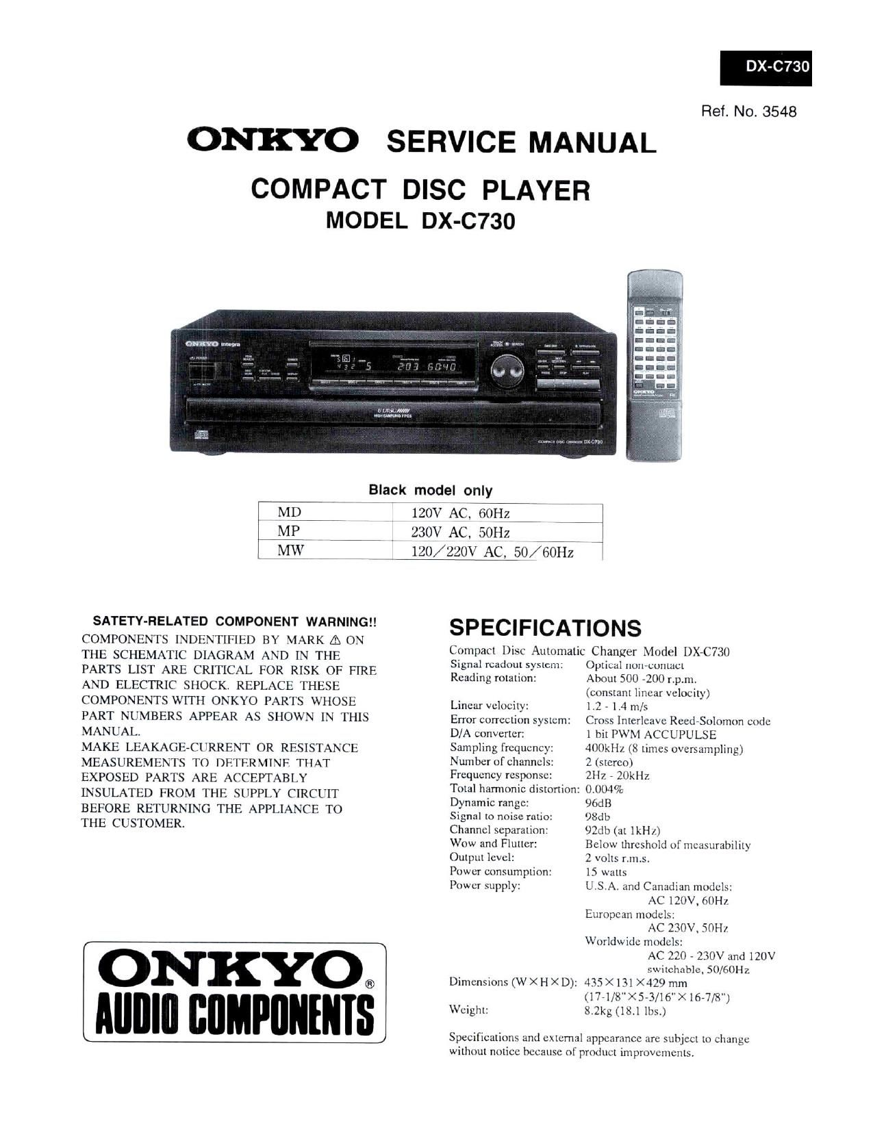
Onkyo DXC 730 Service Manual

Extracted text from Onkyo DXC 730 Service Manual (Ocr-read)


Page 1

730

Ref. No. 3548

ONKYO SERVICE MANUAL
COMPACT DISC PLAYER

MODEL DX-C73O

Black model only

MD
MP

1on AC. 60H;
1 230V AC. 501-12

120/ 220V AC, 750/601-12

SATETY-RELATED COMPONENT WARNING

COMPONENTS INDENTIFIED BY MARK A ON

THE SCHEMATIC DIAGRAM AND IN THE
PARTS LIST ARE CRITICAL FOR RISK OF FIRE
AND ELECTRIC SHOCK. REPLACE THESE
COMPONENTS WITH ONKYO PARTS WHOSE
PART NUMBERS APPEAR AS SHOWN IN THIS

MANUAL.

MAKE LEAKAGE-CURRENT OR RESISTANCE
MEASUREMENTS TO DETERMINF THAT

EXPOSED PARTS ARE ACCEPTABLY

INSULATED FROM THE SUPPLY CIRCUIT
BEFORE RETURNING THE APPLIANCE TO

THE CUSTOMER

Signal rcadnul systcm.
Reading rotation:

Linear velocity:

Error correction system:
D/A converter:
Sampling frequency.
Number ofchanncls'
Frequency response:
Total harmonic distortion:
Dynamic range:

Signal to noise ratio:
Channel separation:
Wow and Flutter:
Output level:

Power consumption:
Power supply:

ONKYO®
lllllllll llflMPllllIllIS

Dimensions (W X H X D):

VVcighl:

SPECIFICATIONS

Compact Disc Automatic Changer Model DXAC730

Opllbdl nuwuutuact
About 500 ~l(l(l r.p.m.
(constant linear Velocity)
1.2 A1,4m/>
Cross [nterleavc Reed-Solnmon code
1 bit PWM ACCUIULSE
40(JkH1. (8 times oversampling)
2 (stereo)
2H2 , 20kHz
0.004%
96:18
98db
92db (at lkHL)
Helnw threshold ul measurability
2 volts r.m,s.
15 wtttts
U S A and Cllnlldmn models:
AC 120V. 60H],
Eumncnn mudcls:
AC 230V, 50H].
Worldwide models:
AC 220 - 230V and 120V
Su'ilcllflblc. 50/60Hz
435 X131><429mm
(1 771/8" >< S-3/16">< 161/8")
1.21:5 (18.1 Ills.)

SpsCtIications and extcmtil appearance :trc subjcct 11) Change

Without notice because til prmluct impruvcmcnts.

Page 2

DX-C73O

TABLE OF CONTENTS

Specification

Service procedure

Caution on replacement of optical pikup
Protection of eyes from laser beam
Laser warning labels

IC block diagram

Microprocessor terminal description
Mechanism exploded view and parts list
Printed circuit PC board parts list
Chassis parts list

Changer mechanism parts list

Chassis exploded view

Block diagram

Adjustment procedure

Printed circuit board view

Packing view

Schematic diagram

Test mode

SERVICE PROCEDURES

1 l. Safety-check out

2 After correcting the original service problemperfonn

2 the following safety check before releasing the set

3 to the customer:

3 Connect the insulating-resistance tester between the

9 plug of power supply cord and chassis.
10 Specifications:More than lOMohm at 500V.
12 2. Voltage Selector (Back panel)
3 Worldwidemodelsareequipped withavoltage sebctor
14 to conform with local power supplieslle sure to set
i: this switch to match the voltage of the power supply
19 in users area before turning the power switch on.
21 Voltage is changed by sliding the groove in the switch
24 with a screw driver to the right or left.
25 Confirm that the switch has been moved all the way to
28 the right or left before turning the power switch on.

| Ell] | [ID
4-- 4--l
220V ~ 120V ~ 220V ~ 120V ~

at ACIZOV at AC'ZZOV

CAUTION ON REPLACEMENT OF OPTICAL PICK UP

During repairearefulley take the following precautions.
sensitive to static electricitysurge current and etc. (The following precautions are included in the service

The laser diode in the optical pickup block is so

that the components are liable to be broken down parts.)

or in reliability remarkably detuiorated.

PRECAUTIONS

1.Ground for the work-desk. 3.Gmunding for the human body.
Place a conductive sheet such as a sheet of copper Be sure to put on a wrist-strap for grounding whose
(with inpedance lower than IOMQ) on the work- other end is grounded.

that the chassis.
2.Grottnding for the test equipment and tools.

in order that their ground level is the same the
ground of the power source.

desk and place the set on the conductive sheet so

Be particularly careful when the workers wear

Test equipments and toolings should be grounded

synthetic fiber clothes. or air is dry.
4.Select a soldering iron thatpennlts no leakage and
have the tip ofthe iron well-gromded.
5.Donotcheckthelaserdiode terminals withthe
probe of a circuit tester or oscilloscope.

Page 14

PACKING VIEW

213

21 o
REF. NO PART NO. DESCRIPTION
201 82115018 5P+18FN, SCREW Accessary bag assy
202 27270382Y 105x15x5.2, SPACER 29100097-IAY 350x250. POLY BAG
206 29053007AY CARTON 2010244Y or PIN CORD AS
207 29091726Y PAD (L) 2010326Y
208 29091727Y PAD (R) 2010200 3.5MIN1 PLUG, CORD AS
209 29100141AY 700x600. POLY BAG - 241403221 RC-322C, REMOTE CONTROLLER
210 29110071 W50. PP TAPE 3010165Y or UM-3, BATTERY
211 282301 STAPLE 3010194Y
214 29095721Y SHEET (DOOR) " 29342309Y INSTRUCTION MANUAL (E)
217 29355207Y INSTRUCTION SHEET 29342310Y INSTRUCTION MANUAL (U6)


218 29360687 LABEL (CLASS 1) 29342311Y INSTRUCTION MANUAL (U3)
29361958Y UPC LABEL 25055040 CV-K-2. CV PLUG
29360840 LABEL (SHEET) 2936501913 WARRANTY CARD
29361786Y LABEL 29358002K SERVICE STATION LIST

29360404 SN SHEET
: 120V model only

: 230V modeI only
: Worldwisbmodelonly

_24_ i