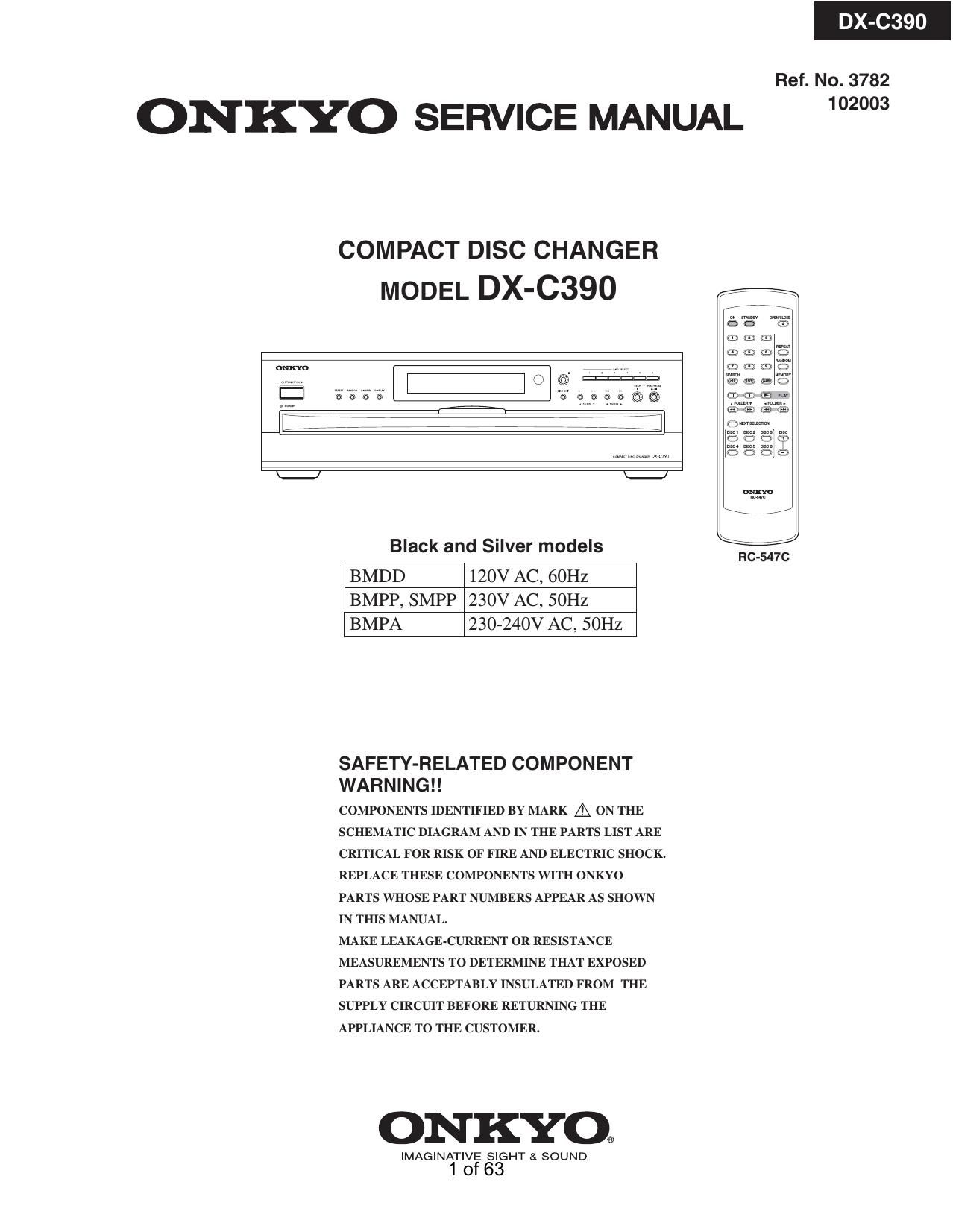
Onkyo DXC 390 Service Manual
This is the 63 pages manual for Onkyo DXC 390 Service Manual.
Read or download the pdf for free. If you want to contribute, please upload pdfs to audioservicemanuals.wetransfer.com.
Extracted text from Onkyo DXC 390 Service Manual (Ocr-read)
Page 1
DX-C390
Ref. No. 3782
ONKYO SERVICE MANUAL 2"
COMPACT DISC CHANGER
MODEL DX-C390
Black and Silver models nc-547c
BMDD 120V AC, 60Hz
BMPP, SMPP 230V AC, SOHZ
BMPA 230-240V AC, SOHZ
SAFETY-RELATED COMPONENT
WA R N I N G ! !
COMPONENTS IDENTIFIED BY MARK A ON THE
SCHEMATIC DIAGRAM AND IN THE PARTS LIST ARE
CRITICAL FOR RISK OF FIRE AND ELECTRIC SHOCK.
REPLACE THESE COMPONENTS WITH ONKYO
PARTS WHOSE PART NUMBERS APPEAR AS SHOWN
IN THIS MANUAL.
MAKE LEAKAGE-CURRENT OR RESISTANCE
MEASUREMENTS TO DETERMINE THAT EXPOSED
PARTS ARE ACCEPTABLY INSULATED FROM THE
SUPPLY CIRCUIT BEFORE RETURNING THE
APPLIANCE TO THE CUSTOMER.
ONKYO®
IMAGINATIVE SIGHT & SOUND
1of63
Page 2
DX-C390
SPECIFICATIONS
DX-CaQO (Compact Disc Changer)
Signal readout system Optical non-contact
Frequency response 5 Hz - 20 kHz
SN ratio 98 dB
Audio Dynamic range 96 dB
THD (Total harmonic distortion) 0.005% (at 1 kHz)
Audio output (Digital/Optical) >22.5 dBm
Audio output/Impedance (Digital/Coaxial) 0.5 V (p-p) / 75 ohm
Audio output/Impedance (Analog) 2.0 V (rms) / 470 ohm
Power supply rating AC 120 V 60 HZ (North American model)
AC 230 V 50 Hz (Other than North American models)
Power consumption 10 W (North American model)
8 W (Other than North American models)
Standby power consumption 4 W
Dimensions (W x H x D) 17-1/8 x 5-3/16" x 17 (435 x 131x 432 mm)
Weight 15.0 lbs. (6.8 kg)
Operating conditions Temperature/Humidity 41-95 OF (535 DC) / 25-80%
Disc compatibility CD, CD-R, CD-RW
RC-547C (Remote Controller)
Transmitter Infrared
Signal range Approx. 16 ft.. 5 meters
Power supply Two (AA/R6) batteries (1.5 V x 2)
Specifications and features are subject to change without notice.
20f63
Page 31
IC BLOCK DIAGRAM/TERMINAL DESCRIPTION
0501 : LC78683E MP3 DECODER FOR CD
Continued from preceding page.
Pin No. Pin Name l/O Block Function
51 DVDD4 Power supply Digital l/O system power supply
52 V55 Ground
53 MADRS7 O DRAM address output 7
54 MADRSS O DRAM address output 6
55 MADRSS O DRAM address output 5
56 MADRS4 O , DRAM address output 4
Memory interface
57 MADRSS O DRAM address output 3
58 MADRSZ O DRAM address output 2
59 MADRSt O DRAM address output 1
60 MADRSO O DRAM address output 0
61 DVDDS Internal logic system power supply
P |
62 V55 ower SUPP y GND
MP3 data request flag output (active high)
63 STREQ V0 /DRAM data request flag input (CD-ROM mode, active high)
MP3 data transfer clock input
64 STCK V0 MP3 stream V0 /DRAM data transfer clock output
MP3 serial data input
65 STDAT V0 /DRAM serial data output
MP3 frame sync signal (active high)
66 FSYNC 0 MP3 dec /Data continuity point detection complete flag (CD-DA mode, active high)
. CRC check result output (CD-ROM data/CD-DA subcode data)
67 CRCF 0 CD monitor /DRAM data output enable signal output (active high)
68 DVDDG Digital l/O system power supply
69 Vss Power supply GND
DRAM write enable input (CD-DA mode, active high)
70 WOK I /DRAM data request flag input
_ Data continuity point detection complete flag (CD-DA mode, active high)
71 CNTOK O Silifligvgkpmm /SYNC error monitor flag (MP3 mode, active high)/DRAM serial data output
DRAM write interrupt flag (CD-DA mode, active high)
72 OVF O /Emphasis output flag (CD-DA and MP3 modes, active high)
/DRAM data transfer clock output
73 CMDOUT 0 Serial command data output (n-channel open-drain output)
74 CMDIN | Serial command data input
75 CL l , Serial command clock input
Microcontroller , ,
76 CE | . Command enable input (active high)
interface Interrupt signal output (active low)
77 INTB O /DRAM write interrupt flag (CD-DA mode, active high)
78 RESB l System reset (active low)
79 DATAIN l CD IF Serial CD data input
80 DATACK | CD bit clock input
Notes: 1. Notes on unused pins.
mun-boa
Unused input pins must be connected to the ground level (0 V).
Unused output pins must be left open. Do not connect anything to these pins.
Unused l/O pins may either be connected to the ground level (0 V) or set to output mode and left open.
the supply levels.)
. The corresponding power supply levels must be provided to all of the DVnot, DVDDS. DVDD4, DVDDG, and AVDD pins. The
corresponding power supply level must also be provided to DVDD2 and DVDDS. (See the Allowable Operating Ranges specifications for
. The TEST1 and TEST2 input pins must be connected to ground (0 V).
. The l/O pins (MDATO:15, STREQ, STCK, and STDAT) go to input mode after a reset.
. After first applying the power supply levels, the RESB pin must be held low for at least 1 ps.
. A 16.9344 MHz clock signal must be supplied to the CKIN pin by the CD DSP.
The LC78684E does not support the implementation of an oscillator circuit using an oscillator element.
31 of 63
390