Onkyo DXC 380 Service Manual

This is the 15 pages manual for Onkyo DXC 380 Service Manual.
Read or download the pdf for free. If you want to contribute, please upload pdfs to audioservicemanuals.wetransfer.com.

Page: 1 / 15
Onkyo DXC 380 Service Manual

Extracted text from Onkyo DXC 380 Service Manual (Ocr-read)


Page 1

Ref.

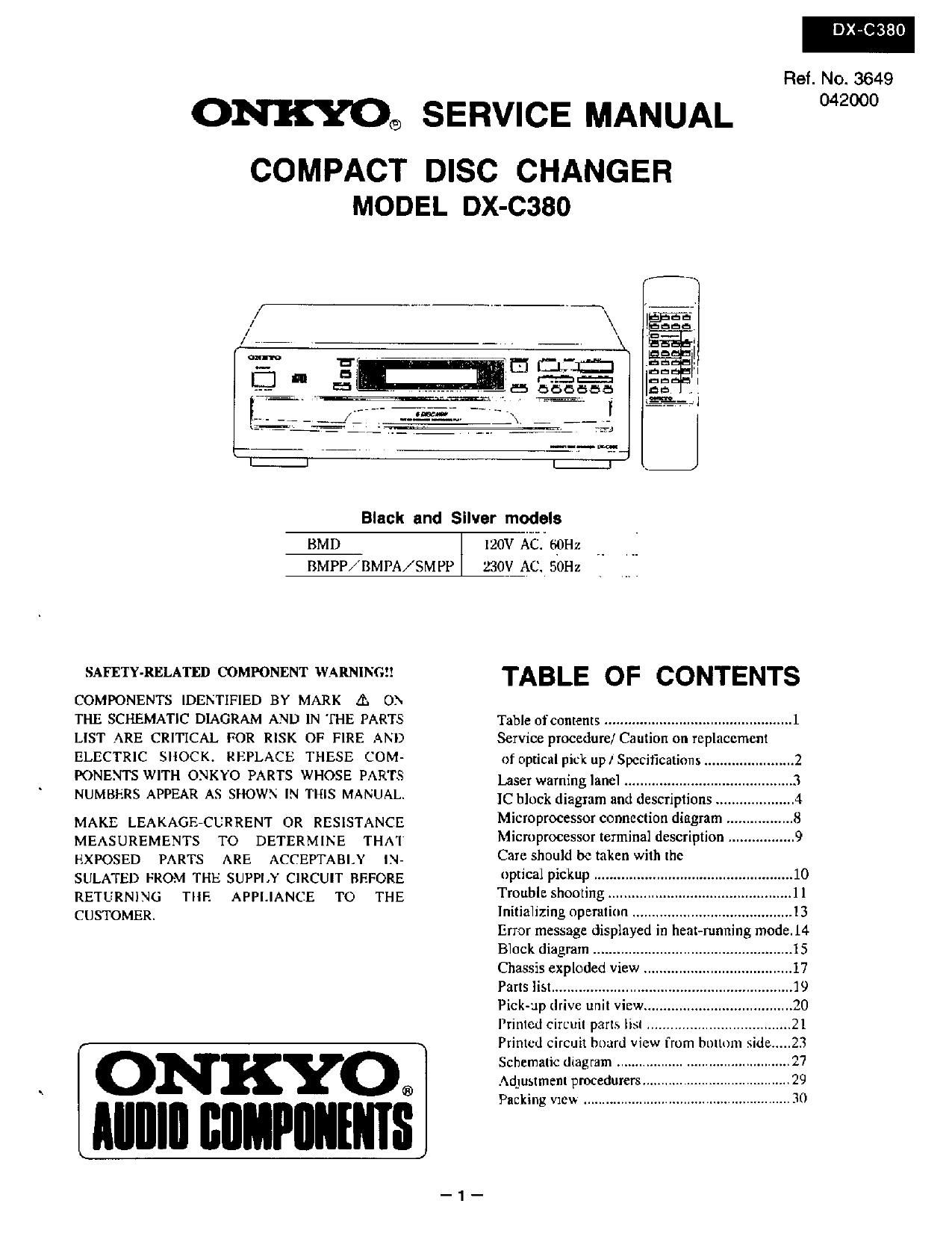
()lq'IIKXC)® SERVICE MANUAL

COMPACT DISC CHANGER
MODEL DX-C380

Black and Silver models

BMD

BMPP/BMPA/SM PP

SAFETY-RELATED LUMPONENT WARNINGH

COMPONENTS IDENTIFIED BY MARK A ON
THE SCHEMATIC DIAGRAM AND IN THE PARTS
LIST ARE CRITICAL FOR RISK OF FIRE AND
ELECTRIC SHOCK. REPLACE THESE COM-
PONENTS WITH ONKYO PARTS WHOSE PARTS
NUMBERS APPEAR AS SHOWN IN THIS MANUAL.

MAKE LEAKAGE-CURRENT OR RESISTANCE
MEASUREMENTS TO DETERMINE THAT
EXPOSED PARTS ARE ACCEPTABLY IN-
SULATED FROM THE SUPPLY CIRCUIT BEFORE
RETURNING TIIF. APPLIANCE TO THE
CUSTOMER.

ONKYO®
IIIIIIII IIIIIIPIIIIIIIIS

120v A . 6sz

230V_AC, 50Hz

TABLE OF CONTENTS

Table of contents ................................................ 1
Service procedure] Caution on replacement

of optical pick up/ Specifications ..
Laser warning lanel ...................
IC block diagram and descriptions
Microprocessor connection diagram
Microprocessor terminal description
Care should be taken with the

optical pickup ......
Trouble shooting
Initializing nperutinn .
Error message displayed in heat-running mode.l4
Block diagram ..........
Chassis exploded View .
Parts list
Pick-up drive unit View,
Printed Circuit parts list
Printed circuit board View from bottom side .
Schematic diagram
Adjustment procedurers.
Packing View

380

N0. 3649
042000

Page 2

DX-C38O

SPECIFICATIONS

Signal readout system:
Reading rotation:

Linear velocity:
Error correction system:

D/A converter:
Sampling frequency:
Number of channel:
Frequency response:

Total harmonic distortion:

Dynamic range:
Signal to noise ratio:
Channel separation:
Wow and Flutter:
Output level:
Power consumption:
Power supply :

Dimensions (W x H x D):

Weight:

Optical non-contact
About 500 - 200 r.p.m.
(constant linear velocity)

[.2 - 1.4 m/s

Cross lnterleave Reed-Rolomon
code

1 bit PWM/ACCUPULSE
352.8 kHz (8 times oversampling)
2 (stereo)

5 llz - 20kHz

0.005% (at tkHz)

96 dB

92 dB

92 dB (at tkHz)

Below threshold ofmeasurability
2 volts r.m.s.

10 watts

120V. 60Hz

230V, 50:

435 x131x 433 mm
(l7<1/8" x 5-3/16" x]7<1/16"
6.9 kg (15.2 lbs.)

Specifications and features are subject to change wuthout

notice.

SERVICE PROCEDURES

1. Safety-check out
After correcting the ongiml service problemperforrn
the following safety check before releasing the set
to the customer.
Connect the insulating-resistance tester between the
plug of power supply cord and chassis.
SpecifmtionsMore than IOMohm at 500V.
Initialize the set.
Roulette stops when the POWER button is
pushed while pushing the button of DlSC6 wit:
DISCl gripped.
Note:
CD mechanism might be damaged to the
movement (transportation) without gripping
DISC.

CAUTION ON REPLACEMENT OF OPTICAL PICK UP

The laser diode in the optical pickup block is so
sensitive to static electricitysurge can-rent and etc.

During repairmfulley take the following precautions.
(The following precautions are included in the service

that the components are liable to be broken down parts.)

or its reliability remarkably deteriorated.

PRECAUTIONS

1.Ground for the work-desk. 3.Grounding for the human body.
Placeaconductivesheetsudtasasheetofoopper Bestuetopmonawflst-strapforgmmdingwhose
(with inpedance lower than IOMO) on the work- otherend is grounded.
deskatdplacethesetontheconductivesheetso Bepanimlarlyearetulwhentheworkenwea
that the chassis. synthetic fiber clothes. or air is dry.

16an for the test equipment and tools. 4.Select a soldering iron that permits no led/age and
Testequipmentsandtoolings shouldbegrounded havethetipottheironwell-mmded.
in order that their ground level is the same the 5.130 not check the laser diode tenninals with the
ground of the power source. probe of a circuit tester or oscilloscope.

Page 6

INITIALIZING OPERATION

DX-C380

I 39 Normal operation
I Q101 When the may closes before POWER
' 36 switch is turned ON.
I 35 FOCUS Stepl-9243-v9-10-r11-S12
TRACKING
SLED
SERVO
AAA 38
le,Q103 33
LASER SW
34
(05 IFOCU§ C) 2
COIL 0105 F0 6 - Q20]
FOCUS
19 TR MICRO-
A IN TRACKING, 13
2515K G SLIDE, ~- PROCESSOR
AND 10 SI.
SPINDLE I ]§
CONTROL
301
4 SP 3 Q
DIGITAL
SPINDLE SIGNAL
: PROCESSOR -
BVNER 5 CH H


M002

LOADING

Q107
LOADING/
CHUCKING
MOTORS
DRIVER

I I . S4LDOPEN
I Mn @ . 53LDCLOSE

M

. . 45 CH OPEN
42 LD OPEN SW

43 LB CLOSE sw


r\
K2.)
@ 41 CH CLOSE SW >
{W \J 40 CH OPEN sw ,
8001 CHUCK G (Travcrse)
--+5v
0001
STOP 5% N O 50 ROT, STOP SENS
6 D
% g 2
3%)C IN A 38 DISC SENSOR
(#3 w >
n 7 01m A 22 ROT L
5b Q108 4 5a -
MOOSJ ROULETTE (1° Sc V 21 ROVER
ROULETTE @ MOTOR R163
@ DRWER
3(NJT2 Q1]0
Q003 GAIN sw 20 ROT. HI
4 NUMBER A a? 53 ROl POS. SENS >
k) U

_13_