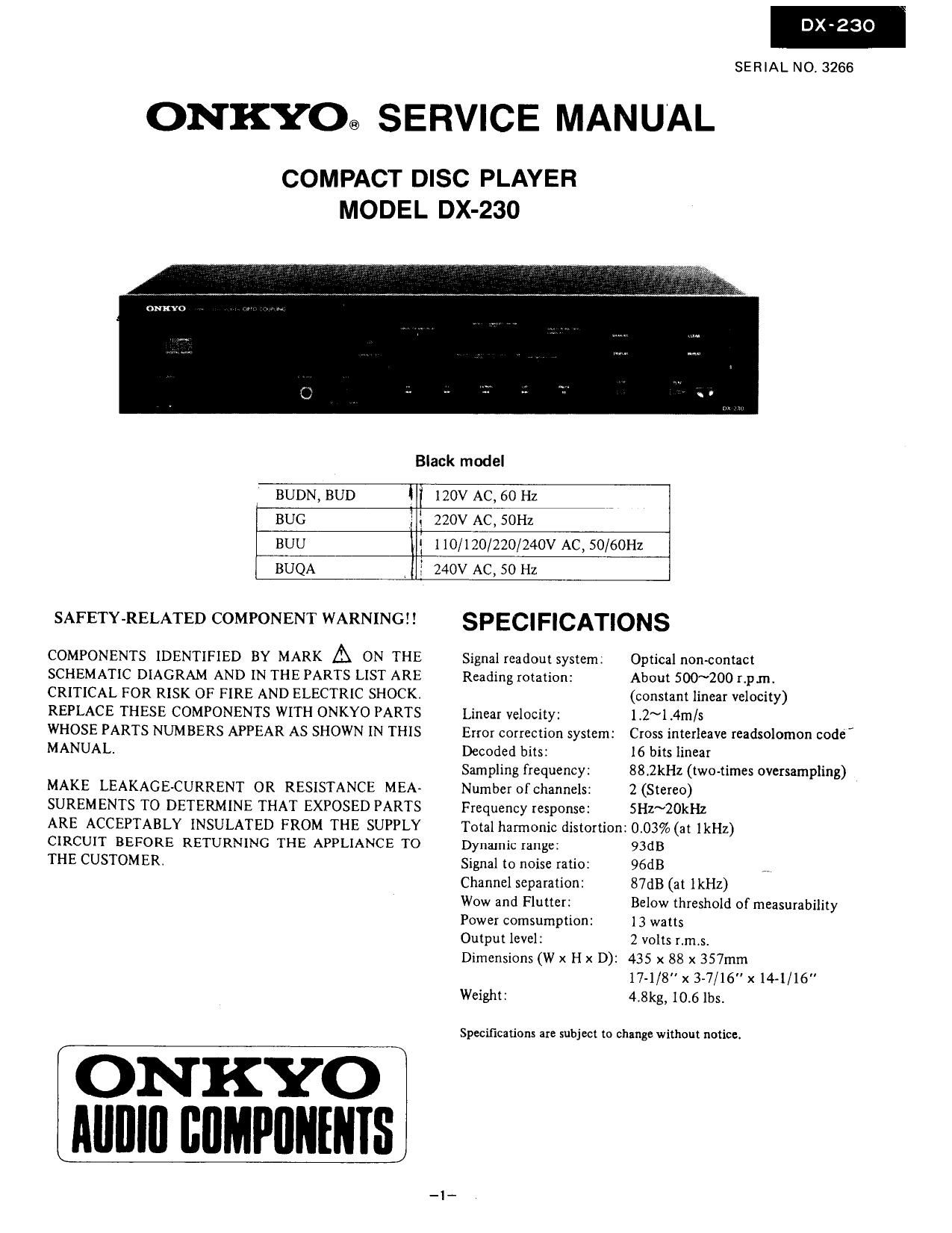
Onkyo DXC 230 Service Manual
This is the 34 pages manual for Onkyo DXC 230 Service Manual.
Read or download the pdf for free. If you want to contribute, please upload pdfs to audioservicemanuals.wetransfer.com.
Extracted text from Onkyo DXC 230 Service Manual (Ocr-read)
Page 1
DX-23O
SERIAL NO. 3266
ONKYO® SERVICE MANUAL
COMPACT DISC PLAYER
MODEL DX-230
Black model
BUDN, BUD I I 120V AC, 60 Hz
BUG = l 220v AC, 50Hz
BUU l 1 10/120/220/240V AC, 50/60Hz
BUQA 240v AC, so Hz
SAFETYtkELATED COMPONENT WARNING SPECIFICATIONS
COMPONENTS IDENTIFIED BY MARK A ON THE Signal readout system. Optical nonfiomact
SCHEMATIC DIAGRAM AND IN THE PARTS LIST ARE Reading rotation: About 500~200 12pm.
CRITICAL FOR RISK OF FIRE AND ELECTRIC SHOCK. (constant linear velocity)
REPLACE THESE COMPONENTS WITH ONKYO PARTS Linear velocity: 1.2~l .4m/s
WHOSE PARTS NUMBERS APPEAR AS SHOWN IN THIS Error correction system: Cross interleave readsolomon code'
MANUAL. Decoded bits: 16 bits linear
Sampling frequency: 88.2kHz (two-times oversampling)
MAKE LEAKAGE-CURRENT OR RESISTANCE MEAA Number ofchannels: 2 (Stereo)
SUREMENTS TO DETERMINE THAT EXPOSED PARTS Frequency response: SH2~20kHz
ARE ACCEPTABLY INSULATED FROM THE SUPPLY Total harmonic distortion; 0.03% (at lkHz)
CIRCUIT BEFORE RETURNING THE APPLIANCE TO Dynamic range: 93dB
THE CUSTOMER. Signal to noise ratio: 96dB
Channel separation: 87dB (at IkHZ)
Wow and Flutter: Below threshold of measurability
Power comsumption: 13 watts
Output level: 2 volts r.m.s.
Dimensions (W x H x D): 435 x 88 x 357mm
17-1/8" x 3-7/16" x 14-1/16"
Weight: 4.8kg, 10.6 lbs.
Specifications are subject to change without notice.
ONKYO
AIIIIIII L'IIMPIIIIIIIIS
Page 2
DX-230
TABLE OF CONTENTS
Specifications ............................ 1
Service procedures ......................... 2
Note on compact disc ....................... 3
Protection of eyes from laser beam .............. 4
Laser warning label ......................... 4
Caution on replacement of pick-up .............. 6
Packing view ............................. 7
Exploded view ............................ 8
Parts list ................................ 9
Mechanism exploded view ................... 10
Parts list ............................... 1 1
Disassembling procedures .................... 12
Circuit descriptions ....................... 14
Trouble shooting guide ..................... 19
IC descriptions ........................... 21
Adjustment procedures ..................... 25
Pc board view from bottom side ............... 26
Schematic diagram ----------------------- 31
Pc board-parts list ......................... 33
Waveform of each seetion .................... 35
Block diagram ........................... 37
SERVICE PROCEDURES
1. Removing the Locking Plate
Locking plate is located on the bottom panel of this unit.
Before using this unit for the first time, the plate must be
removed. If power is switched on while this part is still in
place, the unit will not operate properly
1. Locking plate
2. Tapping screw
Fig.1
2. Safety-check out (U.S.A. model)
After correcting the original service problem, perform the
following safety check before releasing the set to the
customer:
Connect the insulating~resistance tester between the plug
of power supply cable and chassis.
Specifications: more than 10Mohm at 500V.
3. Proceduresfor replacement of flat packaged [Cs
1. Tools to be used:
(1) Soldering iron . . .. Grounded soldering iron or
soldering iron with leak re-
sistance of 10 Mohms or
more.
Form of soldering irons tip:
(2) Magnifying glass . .. for checking of finished
works
(3) TweeLers ........ for handling of IC and
forming ofleads
(4) Grounding ring . . . . Countermeasure for electro-
static breakdown
(5) Nipper ......... for removing defective [C
(6) Small brush ...... for application of flux
2. Work Procedures:
(1) Remove the defective lC
Cut all leads of the defective IC one by one using
a nipper and remove the 1C.
(2) Clean the pattern surface of the PC board.
Get rid of the remaining leads and solder.
(3) Check and from the leads of the new flat packv
aged [C to be installed.
From every lead on the new IC using a pair of
tweezers, so that all of them are aligned neatly
without being risen, twisted or inclined toward
one side. Especially the rising portion of every
lead must be formed with greatest care.
16 IC lc /
gé 3; \E
(Rising) (Twisting) llnclining)
Fig. 3
(4) Apply flux to the PC board.
Apply flux to the pattern surface of the PC board
which has been cleaned, as shown in the illustration.
The area to be applied with flux is the portion of
about 2.5mm in width where the [CS leads are to
be soldered.
Be careful to apply minimum amount of flux
required so as not to smear it on unwanted areas
eases
About 2.5 mm
Fig. 4
Page 6
DX-23O
CAUTION 0N REPLACEMENT OF PICK-UP
lhe laser diode in the optical pick-up block is so sensitive
to static electricity, surge current and etc. that the com-
ponents are liable to be broken down or its reliability
remarkably deteriorated.
PRECAUTIONS
During repair, carefulley take the following precaUtions.
(The following precautions are included in the service
parts).
1. Ground for the work-desk.
Place a conductive sheet such as a sheet of copper
(with impedance lower than 1060) on the work-
desk and place the set on the conductive sheet so
that the chassis.
. Grounding for the test equipment and tools.
Test equipments and toolings shoum be grounded
in order that their ground level is the same the
ground of the power source.
to
Cautions when attaching the optical pickup
PU rack
=sl-li
1) Insert the pickup into the 8-pin socket in accordance
with the red mark direction. If the pickup is inserted
in reverse, the optical pickup will be damaged.
2) Arranged the pickup leads in accordance with the
below view.
3) Use ribbon wire ties to separated the leads.
3. Grounding for the human body.
Be sure to put on a wrist»strap for grounding whose
other end is grounded.
Be particularly careful when the workers wear
synthetic fiber clothes, or air is dry.
Select a soldering iron that permits no leakage and
have the tip of the iron well-grounded.
. Do not check the laser diode terminals with the
probe of a circuit tester or oscilloscope.
Arrange in parallel with ribbon wire
PU rack iastening screws
0+4 \
Wormgear 191 \l:
o r 1
r'w'rr M
Sockets without red mark
NAAR- 274 4-5
{treat 25:36
l/ZELLW
Sockets with red mark
,L-rqim'c
_,-,-"--::/ D
5: ?, 5;»th
After completing the
wiring, turn back the
wire a small amount in
the arrow direction.