Onkyo DXC 101 Service Manual

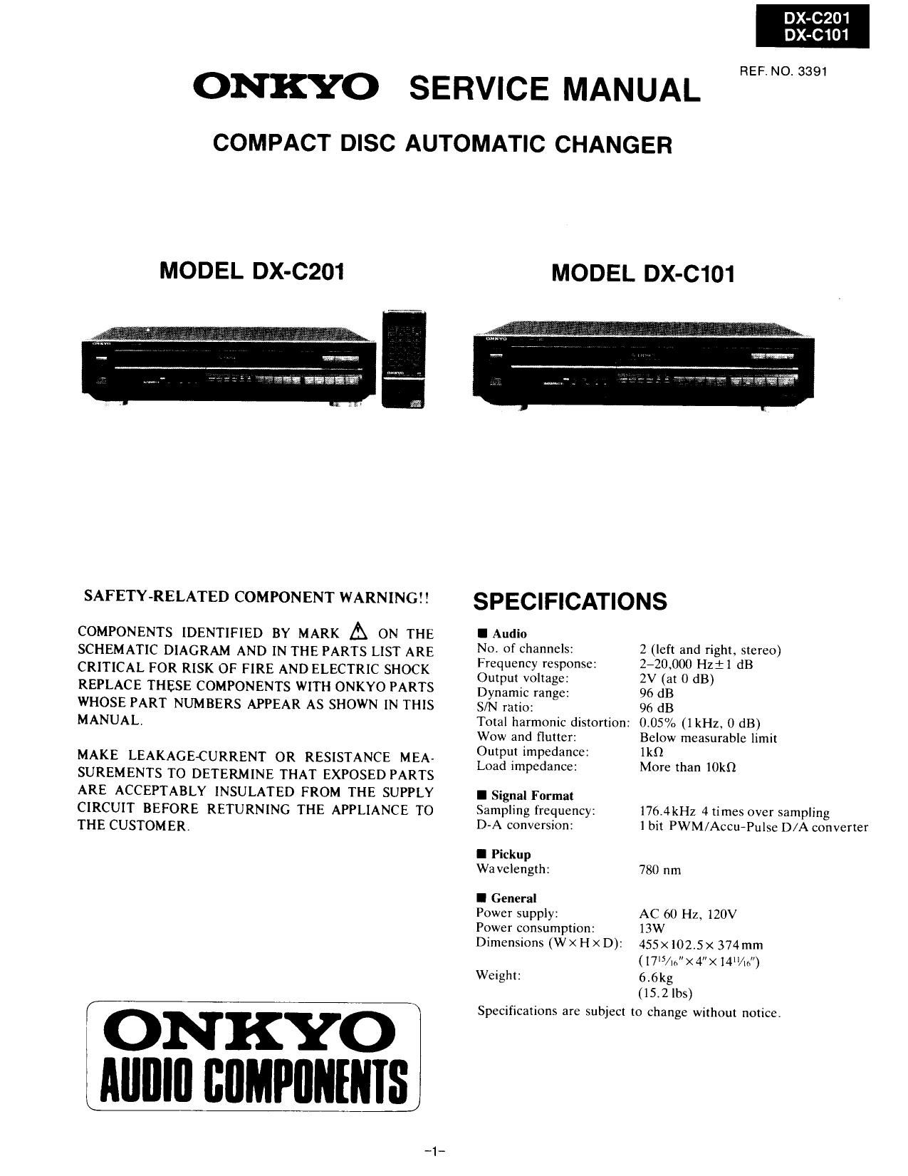
This is the 29 pages manual for Onkyo DXC 101 Service Manual.
Read or download the pdf for free. If you want to contribute, please upload pdfs to audioservicemanuals.wetransfer.com.

Page: 1 / 29
Onkyo DXC 101 Service Manual

Extracted text from Onkyo DXC 101 Service Manual (Ocr-read)


Page 1

DX-C201
DX-C101

REF NO 3391

ONKYO SERVICE MANUAL
COMPACT DISC AUTOMATIC CHANGER

MODEL DX-C201

W

"'.?w an. . .93?

SAFETY-RELATED COMPONENT WARNING! I

COMPONENTS IDENTIFIED BY MARK A ON THE
SCHEMATIC DIAGRAM AND IN THE PARTS LIST ARE
CRITICAL FOR RISK OF FIRE AND ELECTRIC SHOCK
REPLACE THESE COMPONENTS WITH ONKYO PARTS
WHOSE PART NUMBERS APPEAR AS SHOWN IN THIS
MANUAL,

MAKE LEAKAGECURRENT OR RESISTANCE MEA-
SUREMENTS TO DETERMINE THAT EXPOSED PARTS
ARE ACCEPTABLY INSULATED FROM THE SUPPLY
CIRCUIT BEFORE RETURNING THE APPLIANCE TO
THE CUSTOMER.

f ONKYO
Alllllfl BIIMPIIIIIIIIS

MODEL DX-C101

SPECIFICATIONS

I Audio

No. of channels:
Frequency response:
Output voltage:

Dynamic range:

S/N ratio:

Total harmonic distortion:
Wow and flutter:

Output impedance:

Load impedance:

I Signal Format
Sampling frequency:
D-A conversion:

I Pickup
Wa velength:

I General

Power supply:

Power consumption:
Dimensions (W X H x D):

Weight:

2 (left and right, stereo)
240,000 Hzil dB

2V (at 0 dB)

96 dB

96 dB

0.05% (1 kHz, 0 dB)
Below measurable limit
Ikfl

More than IOkQ

176.4kHz 4 times over sampling
1 bit PWM/Accu-Pulse D/A converter

780 nm

AC 60 Hz. 120V
13w

455x1025x 374mm
(1715/.4t><4"><14%")
6.6kg

(15.7. lbs)

Specifications are subject to Change without notice.

Page 2

DX-CZO1
DX-C101

TABLE OF CONTENTS

Specifications ..
Before Use
Precaution of Laser Diode .
Safety Precautions ...............
Handling Precautions for Optica

Diassembling Procedures ...... 6
Terminal Description of IC's . .. 11
Internal Connection of FL . . 15
Troubleshooting Guide . 16
Block Diagram ............. t 19
Printed Circuit Board ~ Parts List . 22
Schematic Diagram ................... u 23
Wiring Connection Diagram ., 30
Printed Circuit Board Views 32
Packing View 35
Exploded View . 36
Parts List 39
Adjustment Procedures ........................ 40

Page 14

101

INDIVIDUAL CONDITIONS

{}

CONTROL BLOCK/MAJOR PART

{}

OBSERVATION POINTS

{}

i
Does focus loop servo N0 Focus error amplifier
operate? lC-101, ICE-102. IC-103
Yes
Does tracking loop servo N0 System CPU circuit
operate? lC-401
Servo control circuit
Y IC-101
Tracking error amplifier
lC-102, iC-103
Optical pickup
Tracking coll
(none repairable)
Does traverse servo operate 2: System CPU circuit =HOW TO CHECK THE TRAVERSE:
correctly? IC~401 *The sound skips every lew
Traverse drive circuit seconds in play mode.
Yes IC-102, IC-103, *Optical pickup moves outward or
IC-toi inward alternately.
Traverse coil *Optical pickup slicks at inner or
outer position,
ls DSL circuit in normal 2°. System CPU circuit
mode? lC-401
Yes
Is RF signal converted by the No Auto gain control circuit =HOW TO CHECK AGC CIRCUIT=
AGC circuit to on ARF signal -> ICA101 * The level oi iC-101 pin ® (ARF
with a constant amplitude? signal) becomes 0.4Vp-p.
I Yes
ls ARF signal converted by 2: Data slice circuit =HOW TO CHECK SRF CiFtCUiT=
DSL circuit to SRF signal? IC-102 * Check (SRF signal) at lC-102 pin @.
I Yes
ls SRF signal synchronized 5: Phase loop circuit =HOW TO CHECK SYNCHRONIZE=
with PCK signal? lC-SOt, IC102 * Check lC-102 pin GD by
oscilloscope in triggered mode with
Yes RF signal and It output waveform at
IC-102 pin ® can be synchronized
ln-phase, the level lC-301 pin @
becomes 2.5 volts.
Is CLV servo changed to 2°. CLV circuit =HOW TO CHECK PHASE
phase-comparison mode? lC-301 COMPARISON:
>t< Check waveform at lC-301 pin 0
Yes (EC signal).
Are both EFM and PCK clock 2: Phase loop lock clrcult =HOW TO CHECK EFM AND PCK=
signal activated? lC-102 =l< Check IC-102 pin ® tor EFM
V waveform.
e5 * Check ic-102 pin a tor PCK
wavetorm.
I 7 No
8 audio signal activated. --> DIA converter circuit
IC-BOI
Yes LPF circuit
lC-BOZ, IGEOS

I NORMAL OPERATION I

'IB-