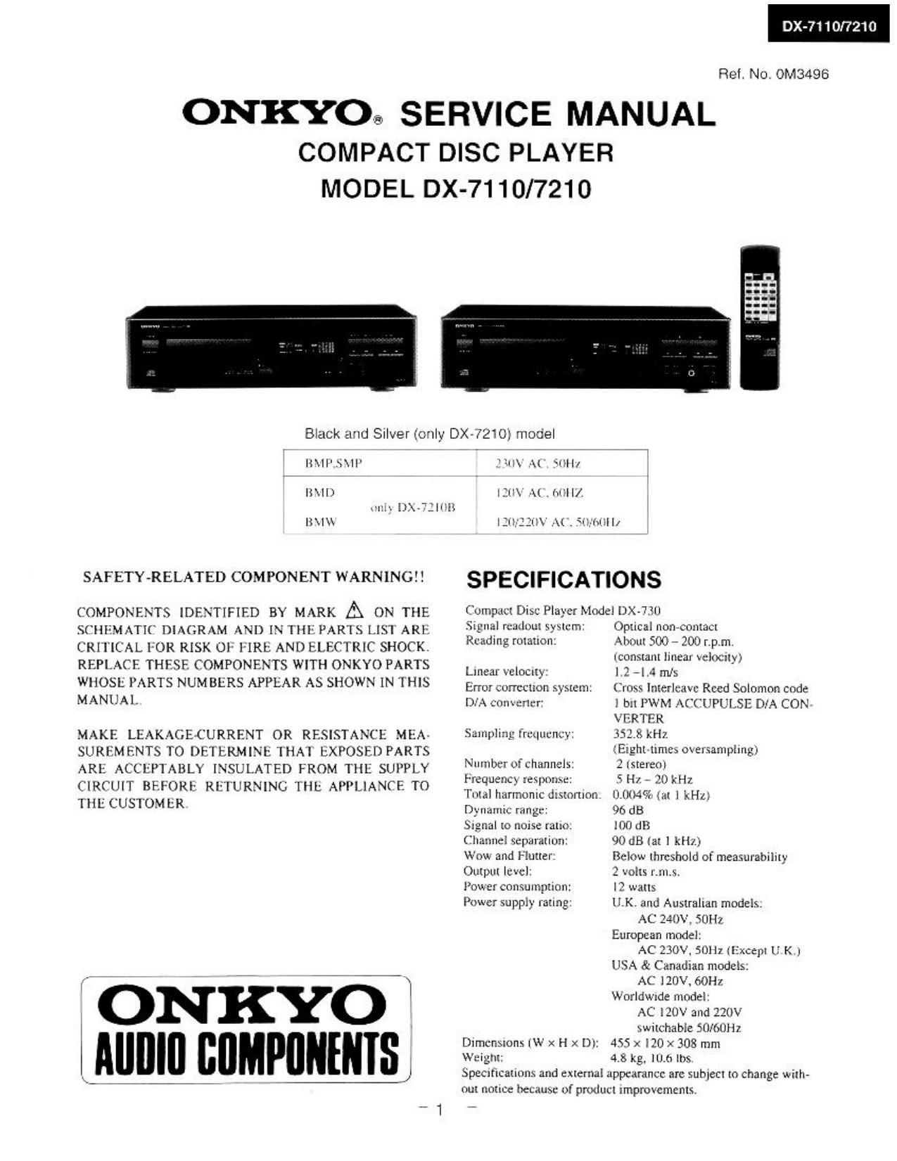
Onkyo DX 7110 Service Manual
This is the 22 pages manual for Onkyo DX 7110 Service Manual.
Read or download the pdf for free. If you want to contribute, please upload pdfs to audioservicemanuals.wetransfer.com.
Extracted text from Onkyo DX 7110 Service Manual (Ocr-read)
Page 2
DX-7110/7210
TABLE OF CONTENTS
SERVICE PROCEDURES
Specifications- - - - ~ - l l. Safety-check out
S°M°° Pmedm ' ' ' 2 After correcting the original service problemperform
calm ° Pm 0f meal PM? 2 the following safety check before releasing the set
Promotion of eyes from laser hem during servicing - 3 m the customer:
Lam warming labels . 3 Connect the insulating-resistance tester between the
EXPIOdFd view . ' . ' . . I ' ~ . I 4 plug of power supply cord and chassis.
Pm 11" f ' 5 Specification52More than 10Mohm at 500v.
Mechanism exploded View . ' 6
Drive mm exploded view 7 2. Voltage Selector (Back panel)
pm us. . . . . 7 Worldwide models are equipped with a voltage selector
Microprocessor connection diagram . . 8 to conform with local power supplieslle sure to set
Micmpmesw Wat description . - 9 this switch to match the voltage of the power supply
IC block diagram and description - - 10~ 13 in user's area before turning the power switch on.
Dissernbling procedure ' - ' ~ ~ ~ ~ ~ - - - 14 Voltage is changed by sliding the groove in the switch
Schematic diagram mechanism block . - - ~ . ~ 15 with a screw driver to the right or left.
Block diagram - . - - - - - - - ' - ~ - ~ ' 16 Confirm that the switch has been moved all the way to
Adjustment procedure ~17.18 the right or left before turning the power switch on.
Printed circuit board view frm bottom side ' - ' 19,20 __
Schematic diagram - -21,22 [ID [ID
Printed circuit board pans list ~ .2324 I
Packing View ' ' . ' 25 > -
220V ~ 120V 220V ~ 120V ~
at ACI2OV at AC220V
CAUTION ON REPLACEMENT OF OPTICAL PICKUP
The laser diode in the optical pickup block is so
sensitive to static electricity,surge current and etc,
that the components are liable to be broken down
or its reliability remarkably deteriorated.
PRECAUTIONS
During repair.carefulley take the following precautions.
(The following precautions are included in the service
pans.)
1.Ground for the work-desk.
Place a conductive sheet such as a sheet of copper
(with inpedance lower than 10MB) on the work-
desk and place the set on the conductive sheet so
that the chassis.
2.Gmunding for the test equipment and tools.
Test equipments and toolings should be grounded
in order that their ground level is the same the
ground of the power source.
3.Grounding for the human body.
Be sure to put on a wrist-strap for grounding whose
other end is grounded.
Be particularly careful when the workers wear
synthetic fiber clothes. or air is dry.
4.Select a soldering iron that permits no leakage and
have the tip of the iron well~grounded.
5.Do not check the laser diode terminals with the
probe of a circuit tester or oscilloscope.
Page 13
SM5872CN (D/A Converter)
MCOM LRCl BCKI D1
63 r? C? Q?
MDT/F8111 11 MICROPROCFSSOR
1 ACE tNPuttIgERI-ACE 5 o
MCK/FSELZ 12 & INFINITY/ZERO C
DE-EMPHASIS DETECTOR
MLEN/DEEM 13 SELECTOR
I IL IR
MUTE 6 ATTENATION
COUNTER Fm PROCESSING
&
T ATTENATION
mocrssmo
RSTN 4 TIMING
CKSL 3 CONTROL
L R -
DVSS 15 l
L I
DVDD 16 GENERATION SHARPER l
BLOCK 1: a: I
4-PROCESSING I
BLOCK 1 xro
L<><}-:-
|
[-
I
PWMDATA -1 NOISE :
I
I
I
|
I
|
I
I
I
AVDDI G
L0 AVSSI LON AVDDZ AVDD3 RON AVSSZ R0
Pin No. Terminal l/O Function Pin No Terminal 1/0 Function
1 XTO O Resonator section 28 KT] l Resonator section
2 XVSS Ground for resonator system 27 XVDD 5V for resonator system
3 CKSL 1 26 AVDDd 5V for analog section
4 CKO 0 Output clock of resonator seetion: 384fs 25 R0 0 R ch PWM output (+I
5 MUTEO O Infinity zero detector output 24 AVSSZ Ground for analog section
6 MUTE] l Mming output 23 RON O R ch PWMoutput (-)
7 MCOM 1 Interface switching control 22 AVDD3 5V for analog section
8 LRCI I Sampling rate clock of mm data: H=L ch, L=R ch 21 AVDDZ iv for analog section
9 BCKI I Bil clock of input data 20 LON O L ch PWM output (+)
10 D1 1 Input data 19 AVSS] Ground {or analog section
11 FSEL1 1 Sampling frequency=44.l kHz 18 LO 0 L ch PWM output (-)
12 FSELZ I When FSEL1.FSEL2. and MCOML are the low level, 17 AVDDl 5V for analog section
13 DEEM l De-emnltasis control input 16 DVDD 5V for digital section
14 RSTN System reset: L=Resct 15 DVSS Ground for digital section
_13_