Onkyo DX 708 Service Manual

This is the 40 pages manual for Onkyo DX 708 Service Manual.
Read or download the pdf for free. If you want to contribute, please upload pdfs to audioservicemanuals.wetransfer.com.

Page: 1 / 40
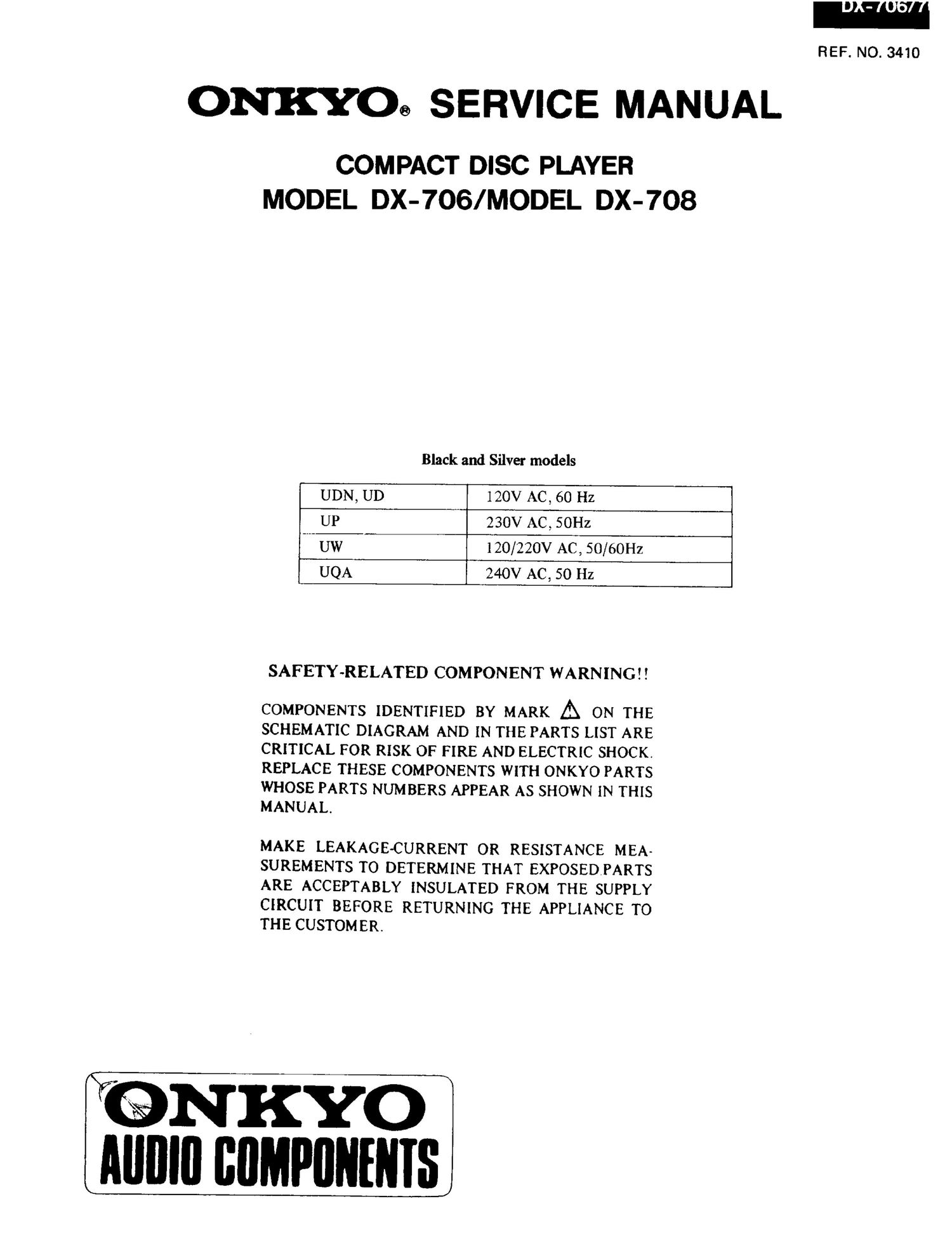
Onkyo DX 708 Service Manual

Extracted text from Onkyo DX 708 Service Manual (Ocr-read)


Page 1

I'o

REF. NO. 3410

ONKYOG SERVICE MANUAL

COMPACT DISC PLAYER
MODEL DX-706/MODEL DX-708

Black and Silver models
UDN, UD 120V AC, 60 Hz
UP 230V AC, SOHz
UW 120/220V AC, 50/60Hz
UQA 240V AC, 50 Hz

SAFETY-RELATED COMPONENT WARNING! I

COMPONENTS IDENTIFIED BY MARK A ON THE
SCHEMATIC DIAGRAM AND IN THE PARTS LIST ARE
CRITICAL POR RISK OF FIRE AND ELECTRIC SHOCK.
REPLACE THESE COMPONENTS WITH ONKYO PARTS

WHOSE PARTS NUMBERS APPEAR AS SHOWN IN THIS
MANUAL.

MAKE LEAKAGE-CURRENT OR RESISTANCE MEA-
SUREMENTS TO DETERMINE THAT EXPOSEDPARTS
ARE ACCEPTABLY INSULATED FROM THE SUPPLY

CIRCUIT BEFORE RETURNING THE APPLIANCE TO
THE CUSTOMER.

N KYO
AIIIIIII BflMPIININIS

Page 2

X-706/708

SPECIFICATIONS

Signal readout system:
Reading rotation:
Linear velocity:

Error correction system:
D/A converter:
Sampling frequency:
Number of channels:
Frequency response:

Total harmonic distortion:

Dynamic range:
Signal to noise ratio:
Channel separation:
Wow and Flutter:

Model DX-706

Optical non~contact

About 500-200 r.pim. (constant linear velocity)
1.24 .4m/5

Cross interleave Reed Solomon code

I BIT PWM X 2 AccuPulse Ouartz System
352.8kHz (eight-times oversampling)

2 (stereo)

2 Hz-20kHz

0.002004 (atl kHz)

100dB

(MB

MIME (all kHz)

Below threshold of measurability

DX-708

Optical non-contact

About 500-200 r.p.m. (constant linear velocity)
1.2-1.4m/s

Cross interleave Reed Solomon code

1 BIT PWM X 2 AccuPulse Quartz System
352.8kHZ (eight-times oversampling)

2 (stereo)

2 Hz~20kHz

0,0020% (atl kHz)

lOOdB

llOdB

llOdB (atl kHz)

Below threshold of measurebility

Output level: 2 volts r.m.s. 2 volts r.m.s.
Power consumption: 21 watts 21 watts
Dimensions (WXHXD): 445Xl30X364mm 455Xl3OX364mm
17-15/16" X 54/8" X 14-5/16' l7-l5/lfi" X 5-1/8" X 14-5/16"
Weight: 8kg, 17.6 lbs. 8.8kg,19.4lbst

Specifications and external appearance are subject to change without notice because of product improvements.

SERVICE PROCEDURES

1. How to Release the Transport Lock

To protect the optical assembly including the laser pickup

from vibration related damage during shipping, this unit is

equipped with a transport lock lever located on the base.

1. Loosen the screw with Phillips screwdriver.

2 Move the lock lever in the direction opposite that shown
by the arrow. Move the lever up to the position where
it can move no farther, and then remove the lever.

I Tighten the screw to secure the lock lever.
I For shipping, restore the lock lever to its position in
the direction of the arrow, then tighten down the
screw to secure the lock lever in that position.

Phillips screwdriver

Loy

Cir
Lock lever

2. Use of batteries

0 The remote control transmitter is powered by two
batteries. Before using this unit for the first time,
insert the two batteries (included).

0 Average battery life is about one year. This period
may be shorter depending on the frequency of use
and environment (temperature and humidity) in
which the remote control transmitter is used.

0 If the remote control transmitter does not operate
even though front panel controls function normally,
the batteries should be replaced. Use only listed in
the following chart.

Type Voltage Site

AA

M35" 1 .5v R6
UM- 3

3. Safety check out

After correcting the original service problem, perform
the following safety check before releasing the set to
the customer:

Connect the insulating-resistance tester between the
plug of power supply cable and chassis.

Specifications: more than 10Mohm at 500V.

4. Voltage selector (rear panel)

Worldwide models are equipped with a voltage selec-
tor to conform with local power supplies.Be sure to
set this selector to match the voltage of the power
supply in your area before turning the power switch
on. Voltage is changed by turning the voltage selector
with a screwdriver or similar instrument to the 120V
or 220V position. Confirm that the selector has been
set to the correct position before turing the power
switch on. If there is no voltage selector switch on the
unit you have purchased, it can only be used in areas
where the power supply voltage is the same as that of
the unit.

Page 16

No. SYMBOL 1/0 DESCRIPTION N0, SYMBOL [/0 DESCRIPTION
1 FOK 1 Focus 0K input 42 DA08 0 DA08 GFS output '
2 st 0 Output tilter changeover output of spindle inotor 43 DA07 o DA07 RFCK output 1
't MON 0 spindle inotor control output 44 DAOG 0 DA06 c2P0 output 771 t
4 MDP 0 Spindle inotor servo control 45 DA05 0 DA05 XRAOF output 7 77* 7 1
5 MDS 0 Spindle inotor servo control 46 DA04 0 DA04 MNT3 output A
6 LOCK 0 H when GFS is high 47 DA03 o DA03 MNTZ output '
7 NC 48 DAOZ 0 DA02 MNTl output .
8 vcoo o oscillation eireuit output tor analog FEM PLL 49 mm o DAOl MNTO output 7 77 (
s) v001 l Oscillation eircuit input for analog EFM PLL I
(8. 543mm) 50 APTR 0 control output lor aperture correction. H when ltch
777% 77Tfi7j Test terininal 51 APTL 0 Control output tor aperture eor7reet7io7n7 H when7l.rli.7
11 Pm 0 Charge purnp output tor analog EFM PLL 52 vss Ground
12 V55 iGround terminal 53 XTAI I crystal oscillation circuit input ot EJHAIMHZ o7i7l
13.15 NC 33.8635814EZ inputr m ..
i 16 VPCO 0 PLL charge pu7mp output tor variable pitch 54 XTAO o Crysta7l oscllmd cirouit output ot 16 9347411712
. l7 VCKI 1 Clock input tor variahle pitch tron. vco 55 1 XTSL 1 Crystal selection input terminal Lwhen 7
L (16 934MHz) 16.9344MH2 H when 3:1 8688MH2 A
l 18 1 Flu) 0 Filter output lor inaster PLL 56 FSTT 0 2/3 divided output ot pins 5:; & 54 A
l 19 Flu I Filter input tor master PLL 57 CAM o 4 .tiMl-lz output . . 7'
l PCO 0 Charge punip output for master PLL 58 cum 0 16, 57344an output 7
AVss Analog ground 59 mm 1 Digital output control input on at H at ()[f at L 7
CLTV I VCO conlml voltage input for master 60 DOUT 0 Dlgltal output
AVDD Analog section power supply(+EiV) 61 EMPH 0 Emphasis oontrol output. Retire H
RF 1 EFM signal input 62 WFCK 0 Write traine oloolt output 77 W . d
25 TESTZ 1 connect to the ground. 63 SCOR o Sulrcode detection7ou7tput, H when is detected so or
26 TESTS 1 connect to the ground. 51.
27 ASYO o EFM lull swing output 64 SBSO 0 Serial output ot sub code(P~W) 7
23 113514 I Connect to the ground. 65 1:ch I Clock input tor read out SBSO T
29 NC 66 SQSO 0 Sub Q 80 hits. PCM peak. and level data lti bits
30 PSSL 1 Audio data output mode changeover input. output { 77 W
Serial data at L and paraller data at H. 67 SQCK 1 Clock input for read out 505317777 7 J
31 WDCK o D/A intertace tor 48 hits slot. word clock Hrs 68 MUTE o Muting control output Aetive H.
32 LRCK o D/A intertace tor ts hits slot. LR oloolt f:Fs. 69 SENS r Sens output. output to microprocessor
33 VDD Power supply terininalt+5vl 7o XRST 1 System reset. Rest at low level. 7
34.49 Data output terminals 70 DATA 1 Serial data input lroin microprocessor 7
PSSL=1 PSSL20 72 XLTA l Lateh input iroin microprocessor, Latch the serial
34 DAlfi 0 DA16 Serial data ot 48 bits slot data at trailing. l
35 DAls o DA15 Bit clockof 43 hits slot 73 VDD Power supply 7
36 DA14 0 DAN serial data ot 64 hits slot 74 CLOK 1 Serial data transler clock input tron. microprocessor
37 DA13 o DA13 Bit clock oi 68 hits slot 75 SEIN l Sens input troni SSP 7
38 DAIZ o DAIZ LR clool of 68 hits slot 76 CNCI 1 Track iuinp numbers count signal input
39 mm 0 DAN GTOP output 77 DATO 0 Serial data output to SSP
40 DAIO 0 DAIO XUGF output 78 XLTO 0 Serial data latch output to SSP, Latch at trailing 3
41 mos 0 DADS XPLCK output 79 CLKO 0 Serial data transter elool output to SS? 4
so MIRR 1 Mirror signal input 1

Note:SSP:Q104 CXA137ZS

-16_