Onkyo DX 700 Service Manual
This is the 26 pages manual for Onkyo DX 700 Service Manual.
Read or download the pdf for free. If you want to contribute, please upload pdfs to audioservicemanuals.wetransfer.com.
Extracted text from Onkyo DX 700 Service Manual (Ocr-read)
Page 1
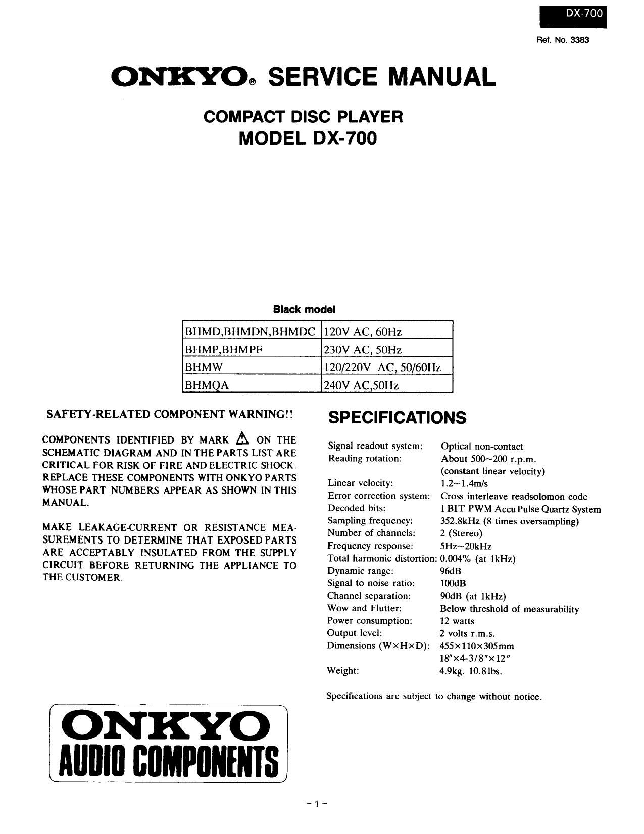
DX-7OO
R64. No. 3383
ONKYOG SERVICE MANUAL
COMPACT DISC PLAYER
MODEL DX-700
Black model
BHMD,BHMDN,BHMDC 120V AC, 60Hz
BHMP,BHMPF 230V AC, SOHz
BHMW 120/220V AC, 50/60Hz
BHMQA 240V AC,50Hz
SAFETY-RELATED COMPONENT WARNING SPECIFICATIONS
COMPONENTS IDENTIFIED BY MARK A ON THE
SCHEMATIC DIAGRAM AND IN THE PARTS LIST ARE
CRITICAL FOR RISK OF FIRE AND ELECTRIC SHOCK.
REPLACE THESE COMPONENTS WITH ONKYO PARTS
WHOSE PART NUMBERS APPEAR AS SHOWN IN THIS
MANUAL.
MAKE LEAKAGE-CURRENT 0R RESISTANCE MEA-
SUREMENTS TO DETERMINE THAT EXPOSED PARTS
ARE ACCEPTABLY INSULATED FROM THE SUPPLY
CIRCUIT BEFORE RETURNING THE APPLIANCE TO
THE CUSTOMER.
ONKYO
Allnlu chlefms
Signal readout system:
Reading rotation:
Linear velocity:
Error correction system:
Decoded bits:
Sampling frequency:
Number of Channels:
Frequency response:
Total harmonic distortion:
Dynamic range:
Signal to noise ratio:
Channel separation:
Wow and Flutter:
Power consumption:
Output level:
Dimensions (WXHXD):
Weight:
Optical non-contact
About 500~200 r.p.m.
(constant linear velocity)
1.2~1.4m/s
Cross interleave readsolomon code
1 BIT PWM Accu Pulse Quartz System
352.8kHz (8 times oversampling)
2 (Stereo)
5Hz~20kHz
0,004% (at lkHz)
96dB
IOOdB
90dB (at lkl-Iz)
Below threshold of measurability
12 watts
2 volts r.m.s.
455x110x305mm
18"X4-3/8"><12
4.9kg. 10.8lbs.
Specifications are subject to change without notice.
Page 2
DX»700
TABLE OF CONTENTS
Specifications .............. .........................1
SerVice procedures --
Note on compact disc ..................................2
Caution of replace-em of optical pickup ...... -------- 3
Protection of eyes from laser bea- during servicing "'4
Laser warning label ....... ....................... .4
Mechanisn exploded view -
Exploded viev ..
Parts list .....................
lC block diagrams and descriptions ..........
one.
Printed circuit board view
Pr: board-parts list an"
Schematic diagram ....................
Block diagral ...............
NOTE ON COMPACT DISC
0 Holding Compact Discs
Hold Compact Discs by the edges so that you do not touch
the surface of disc. Remember that the side of the disc with
the rainbow" reflection is the side containing the audio
information.
Do not attach tape or paper to the label side of the disc
and always be careful not to leave fingerprints on the side
that is played.
0 Storing Compact Discs
Store Compact Discs in a location protected from direct
sunlight, high heat and humidity and extremely high
and low temperatures. Discs should never be left in the
trunk or interior of an automobile in the sun since the
temperature can become very high in such a closed environ-
ment,
Always store Compact Discs in the holders in which they
were sold. Never leave a disc in the players disc holder for
along period of time.
Nor this way
SERVICE PROCEDURES
1. Safety-check out
After correcting the original service problemperform
the following safety check before releasing the set
to the customer:
Connect the insulating-resistance tester between the
plug of power supply cord and chassis.
SpecificationszMore than lOMohm at 500V.
2. Voltage Selector (B ack panel)
Worldwide models are equipped with a voltage selector
to conform with local power supplies.Be sure to set
this switch to match the voltage of the power supply
in user's area before turning the power switch on.
Voltage is changed by sliding the groove in the switch
with a screw driver to the right or left.
Confirm that the switch has been moved all the way to
the right or left before turning the power switch on.
[ID ED
220V ~ 120V N 220V ~ 120V N
at ACIZOV at AC220V
0 Cleaning Compact Discs
Before playing a disc wipe off the playing surface with a
soft cloth to remove dust and other soil. Wipe the surface
in straight lines from the center of the disc outward, not
in a circular motion as you would with a phonograph
record.
Do not use benzene, chemical cleansers or phonograph
record cleaning solutions to clean Compact Discs. Also
avoid static electricity prevention solutions since they can
damage the surface of Compact Discs.
Problems Caused by Dew
Dew can form inside a Compact player when it is brought
from a cold environment into a warm roomI when a room
is rapidly heated and if a player is left in ahumid environ-
ment
This dew can prevent the laser pickup from reading the
data contained in the pits in the disc surface. If the player
does not operate properly because of dew, remove the disc
and leave the players power switch on for about one
hour to remove all moisture.
Page 5
MECHANISM-EXPLODED VIEW
PICKUP DRIVE UNIT-EXPLOVED VIEW
PARTS LIST
REF.NO. PART NO. DESCRIPTION REENO, PART NO. DESCRIPTION
1 24506900 Slide shaft 10 24506904 thcl B
2 24110008 KSS-210A.Oplieal pickup 11 801427 STP2.6 >< 8.Special screw
3 801425 S2 >< 5.5pecial screw 12 24506905 Shaft clamp
4 24506901 Slide holder 13 24502263 Spindle motor ass'y
5 821 12005 P2 >< 5,Pan head screw 14 25065403 N LF-lZZOJxafswilch
6 24506902 Gear cover 15 24505271 Motor pc board
7 24502262 Sled molor ass'y 16 25050396 NSCT-4P223,Sockc[
8 801426 ML7 X 3,Special screw 17 24506906 Stopper
9 24506903 Wheel A
Page 14
NOu SYMBOL [/0 DESCRIPTION No. svuuot 10 DESCRIPTION
1 FOX I Focus 0K input 42 DAUB 0 mos GFS output
2 st 0 output tilter changeover output oI spindle tnotor 43 BAN o DA07 RFCK output
3 MON 0 Spindle mnlor oontrol output 44 mm; o DADS CZPO output
4 MDP o spindle ntotor servo control 45 was 0 mos XRAOF output
5 MDS 0 spindle ntotor servo control 7 46 W Min 0 DA04 ileTa oulpul
5 LOCK o H when GFS is high 47 13.403 0 mm MNTZ output
_A7 NC 48 moz 0 DAOZ thTI output
a vcoo 0 Oscillalion circuit output tor analog FEM PLL 49 DAOI o DAOI MNTO output
9 VCOI I Oscillation cimui! input tor analog EFM PLL "-7
(8.6436MH2) 50 APTR 0 Control output tor aperture correction H when Rch.
~10 TEST I Test termiunl 51 531:1 0 Control output for aperture con-eclion. H when Lch.
II PDO '6 Charge putnp output tor analog EFM PLL 52 yss and
l2 Vss Ground tertninnl 53 XTAI I crystal oscillaliou eirouit input oI 16. 934mm or
13-15 NC 33. otuaMllz input
l6 v1>co o PLL oharge purnp output tor variable pitch 54 XTAU 0 Crystal ion tireuit output oI l6. 9344MH1
7 l7 VCK] I Clock input tor variable pilch Iron. vco 55 fig? T E}:;t;fseleclio nput ter;irtal. I. when 7
(16.934MH2) lo 9::l4MIle. H when 33.84IBBMH1
7 0 Filter output tor master ILL 56 FSTT 0 m tin-turd output oi pins 53 at 5.4
' l Filter input Ior ntaster PLL 7 57 A UM W 6 «shill; output -_ _-,,..._..._ WW
0 Charge pump output Iortnnster P1,]. so ' Thiilznutput 77W " " WWW'W
1: Analog ground 59 MDZ l Digital output rontrol .nput on; H at on at 1..
22 l vco control voltage input tor master on BOUT __ 7
' 23 Analog section power supply(+5v) til EMPII utnphas conlrol nulpul. Active H. 7
24 I EFM signal input 62 A 5 write hi. flocking?-
25 I Connect to the ground - 63 "5 Sui-code deIEJfimpfiiHiwhen is detected so or
2o I Connect to the ground. S].
_37 o EFM lull swing output 64 $350 0 Seria| output oi sub cnde(P~W)
28 1 Connect to the ground. 65 EXCK I Clocli input tor read out 5350
29 so soso 0 suit Q 80 bits. PCM peilt. and level datn 16 hits
30 I Audio data output nutde changeover input. output
serial data at L and paraller data at H. 67 Clock inpu_t Ior read out 5050
31 wncx 0 WA inlerlace tor 43 bits slot. Word clock t:2Fs. 68 hluting fltrol oulpllt Active ll.
32 LRCK 0 0M interlure tor 48 hits slot LR clock l=Fs. GS) sens uulpu; output to microprocessor 7
33 VI)[) Power supply terminalt+5Vl 70 Syslem reset. Rest nt lnw level,
3419 Data output terminals 70 Serial data input [rum microprocessor
PSSL=I PSSL=0 72 Lalch input Irnrn microprocessor. Latch the serial
34 DA16 o DMG Serial data at 43 bits slot data it trailing.
:45 DA15 0 mus Bit clock'of 48 hits slot 73 von Power supply
so 9514 0 DAN serial data oi 64 bits slot 74 cum 1.. serial int: trsnsrer clock inp_ut Iron misrlflrgclflrfl
:37 l)Al3 0 mild Bit clock oi 68 hits slot 75 w>sulN ;_lA Sens input {run 551 __ 7 W
36 W 0.412 0 0m LR clock ot 68 Itits slot 76 CNC] I Track jump numbers cuunl signal input
» 39 DA]! 0 0M] GTOP output 77 DATO 0 serial data output to SSP
40 DMO o DAIO XUGF output 78 XLTO 0 Serial data latch output to ssr. Ltteh at trailing.
41 DAOQ 0 DA09 XPLCK output 79 CLKO 0 Serial data transfer clock output to SSP
so MIRR l Mirror signal input
Note:SSPzQ104 CXA137ZS
-13-