Onkyo DX 6800 Service Manual

This is the 20 pages manual for Onkyo DX 6800 Service Manual.
Read or download the pdf for free. If you want to contribute, please upload pdfs to audioservicemanuals.wetransfer.com.

Page: 1 / 20
Onkyo DX 6800 Service Manual

Extracted text from Onkyo DX 6800 Service Manual (Ocr-read)


Page 1

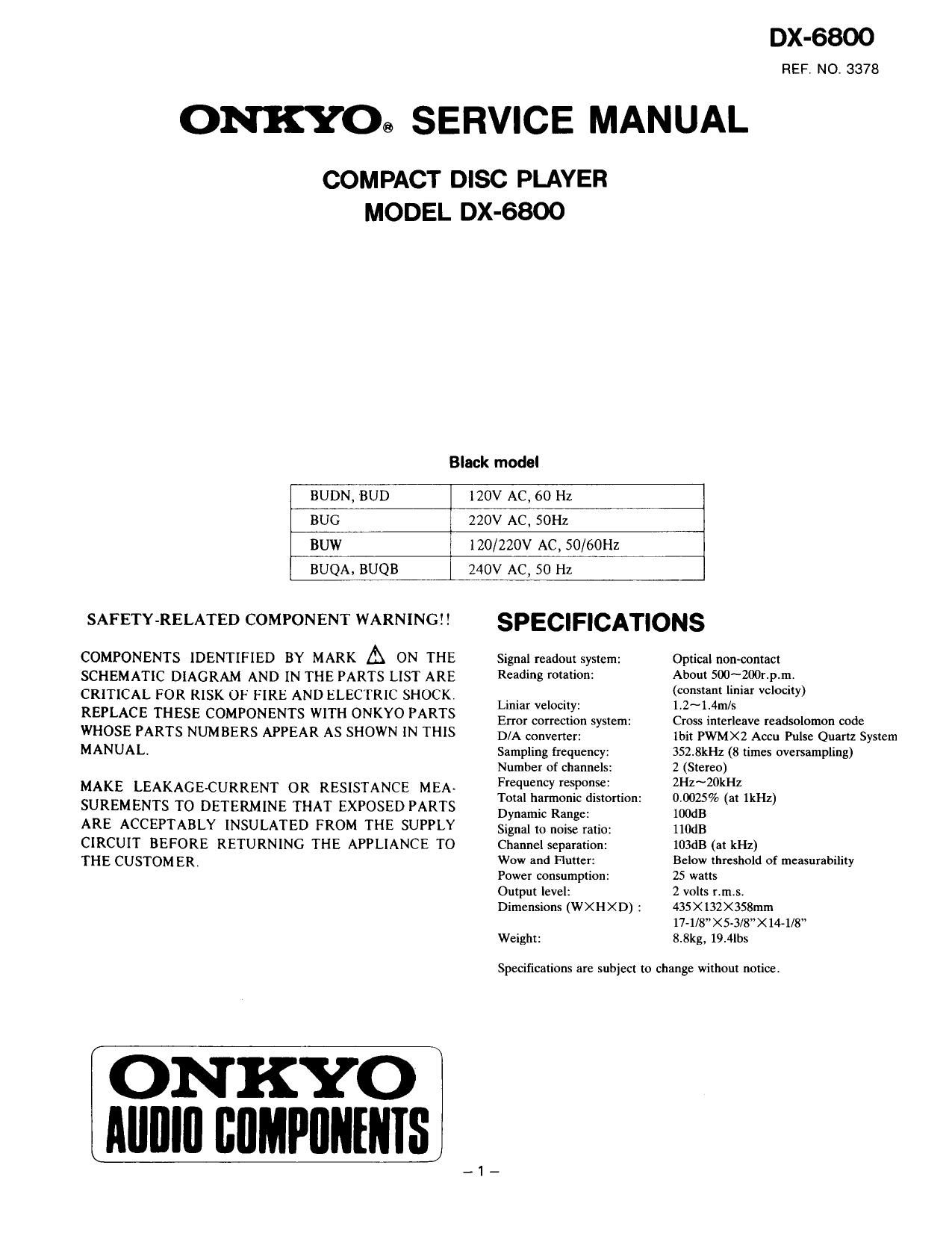
DX-6800

REF. NO. 3378

ONKYO® SERVICE MANUAL

COMPACT DISC PLAYER
MODEL DX-6800

Black model

BUDN, BUD

120V AC, 60 Hz

BUG

220V AC, SOHI.

BUW

l20/220V AC, 50/60Hz

BUQA. BUQB

240v AC, so Hz

SAFETY-RELATED COMPONENT WARNING! I

COMPONENTS IDENTIFIED BY MARK A ON THE
SCHEMATIC DIAGRAM AND IN THE PARTS LIST ARE
CRITICAL FOR RISK OF FIRE AND ELECTRIC SHOCK
REPLACE THESE COMPONENTS WITH ONKYO PARTS
WHOSE PARTS NUMBERS APPEAR AS SHOWN IN THIS
MANUAL

MAKE LEAKAGEvCURRENT OR RESISTANCE MEA-
SUREMENTS TO DETERMINE THAT EXPOSED PARTS
ARE ACCEPTABLY INSULATED FROM THE SUPPLY
CIRCUIT BEFORE RETURNING THE APPLIANCE TO
THE CUSTOMER.

ON KYO
IIIIIIIII BflMPlIIIIIIIS

SPECIFICATIONS

Signal readout system:
Reading rotation:

Liuiar velocity:

Error correction system:

D/A converter:

Sampling frequency:
Number of channels:
Frequency response:

Total harmonic distortion:

Dynamic Range:
Signal to noise ratio:
Channel separation:
Wow and Flutter:
Power consumption:
Output level:

Dimensions (WX H XD) :

Weight:

Optical non-contact

About 500~200r.p.m.

(constant liniar velocity)
1r2~1.4m/s

Cross interleave readsolomon code
lbit PWMXZ Accu Pulse Quartz System
352.8kHz (8 times oversampling)

2 (Stereo)

2Hz~20kHz

0.005% (at lkHz)

100dB

llodB

103dB (at kHz)

Below threshold of measurability
25 watts

2 volts was

435 X 132X3S8mm

17-1/ "XS-3/8><14-1/8"

8.8kg, 19.4le

Specifications are subject to change without notice

_1_

Page 2

TABLE OF CONTENTS

Specifications ........................................................
Service procedures .........
Laser warning label .......
Chassis-exploded View .. ..
Parts list ......................
Mechanism-exploded view. . ..
Parts list ........................
Caution on replacement of pickup ............................ 3
Protection of eyes from laser beam during servicing ..... 8
IC block diagrams and descriptions.
Adjustment procedures .................
Pc board views .............................

DAC and audio circuit pc board ..

Digital circuit pc board..

Other pc boards ...........
Pc board-parts list .
Block diagram ...... ..
Packing view ...................................................... 31

H


SERVICE PROCEDURES

1. How to Release the Transport Lock

To protect the optical assembly including the laser pickup

from vibration related damage during shipping, this unit is

equipped with a transport lock lever located on the base.

1. Loosen the screw with Phillips screwdriver.

2. Move the lock lever in the direction opposite that shown
by the arrow. Move the lever up to the position where
it can move no farther, and then remove the lever.

I Tighten the screw to secure the lock lever,
O For shipping, restore the lock lever to its position in
the direction of the arrow, then tighten down the
screw to secure the lock lever in that position.

Phillips screwdriver

L OCR
Lock lever

2. Use of batteries

0 The remote control transmitter is powered by two
batteries. Before using this unit for the first time,
insert the two batteries (included).

0 Average battery life is about one year. This period
may be shorter depending on the frequency of use
and environment (temperature and humidity) in
which the remote control transmitter is used.

0 If the remote control transmitter does not operate
even though front panel controls function normally,
the batteries should be replaced. Use only listed in
the following chart.

Type Voltage Size

AA

MTS 1.5V R6
" UM»3

3. Safety check out

After correcting the original service problem, perform
the following safety check before releasing the set to
the customer:

Connect the insulating-resistance tester between the
plug of power supply cable and chassis.

Specifications: more than 10Mohm at 500V.

4. Voltage selector (rear panel)

Worldwide models are equipped with a voltage selec-
tor to conform with local power supplies. Be sure to
set this selector to match the voltage of the power
supply in your area before turning the power switch
on. Voltage is changed by turning the voltage selector
with a screwdriver or similar instrument to the 120V
or 220V position. Confirm that the selector has been
set to the correct position before turing the power
switch on. If there is no voltage selector switch on the
unit you have purchased, it can only be used in areas
where the power supply voltage is the same as that of
the unit.