Onkyo DX 5700 Service Manual
This is the 22 pages manual for Onkyo DX 5700 Service Manual.
Read or download the pdf for free. If you want to contribute, please upload pdfs to audioservicemanuals.wetransfer.com.
Extracted text from Onkyo DX 5700 Service Manual (Ocr-read)
Page 1
SERIAL NO. 3352
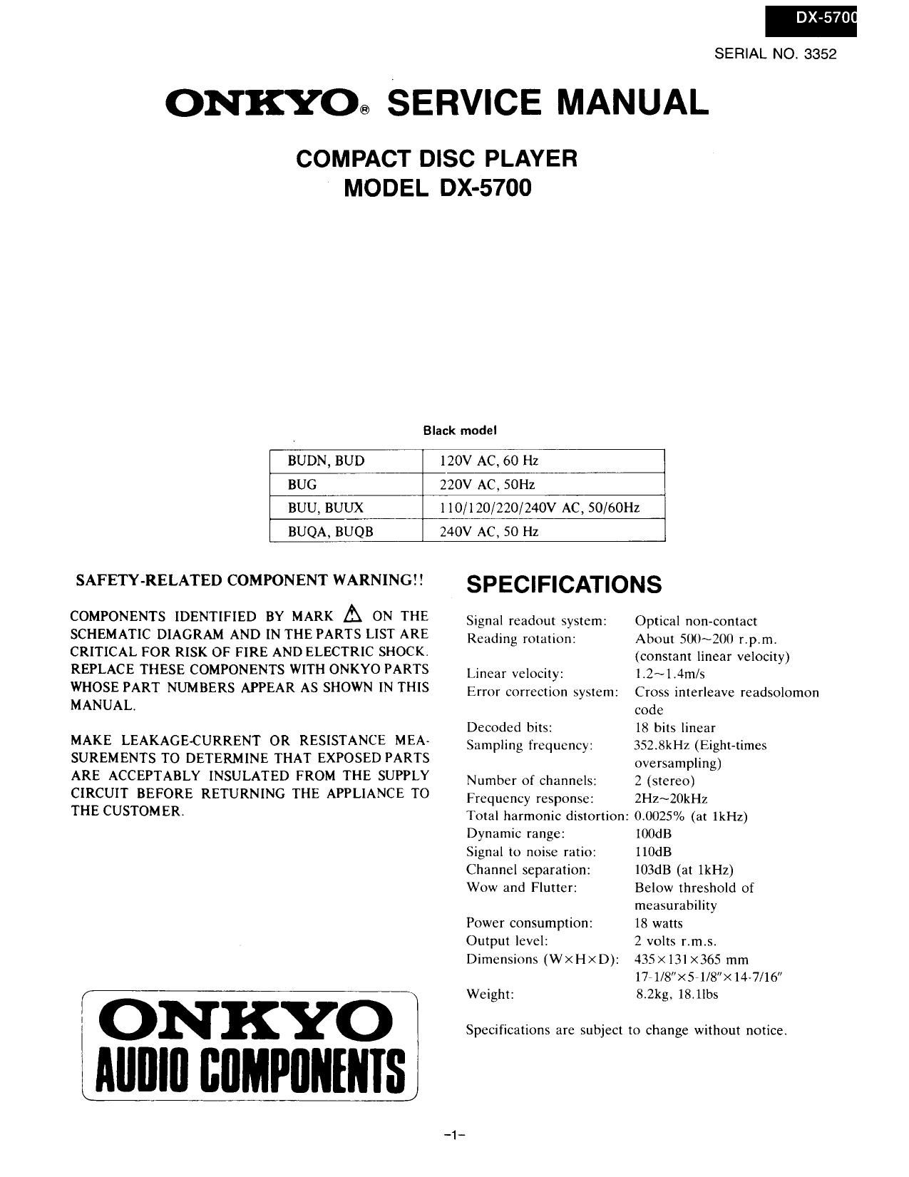
ONKYO® SERVICE MANUAL
COMPACT DISC PLAYER
MODEL DX-5700
Black model
BUDN, BUD
120V AC. 60 Hz
BUG
220V AC, SOHz
BUU, BUUX
l10/120/220/240V AC, 50/60Hz
BUQA, BUQB
240V AC, 50 Hz
SAFETY-RELATED COMPONENT WARNING
COMPONENTS IDENTIFIED BY MARK A ON THE
SCHEMATIC DIAGRAM AND [N THE PARTS LIST ARE
CRITICAL FOR RISK OF FIRE AND ELECTRIC SHOCK.
REPLACE THESE COMPONENTS WITH ONKYO PARTS
WHOSE PART NUMBERS APPEAR AS SHOWN IN THIS
MANUAL.
MAKE LEAKAGE-CURRENT OR RESISTANCE MEA-
SUREMENTS TO DETERMINE THAT EXPOSED PARTS
ARE ACCEPTABLY INSULATED FROM THE SUPPLY
CIRCUIT BEFORE RETURNING THE APPLIANCE TO
THE CUSTOMER.
ONKYO I,
JIIIIlIu BUMPnutNIsI
SPECIFICATIONS
Signal readout system:
Reading rotation:
Optical non-contact
About 500~200 r.pim.
(constant linear velocity)
Linear velocity: l.2~l,4m/s
Error correction system: Cross interleave readsolomon
code
Decoded bits: 18 bits linear
Sampling frequency: 352.8kHz (Eight-times
oversampling)
Number of channels: 2 (stereo)
Frequency response: 2H2~20kHz
Total harmonic distortion: 0,0025% (at 1kHz)
Dynamic range: lOOdB
Signal to noise ratio: IIOdB
Channel separation:
Wow and Flutter:
103dB (at IkHz)
Below threshold of
measurability
18 watts
2 volts r.m,si
435x13] X365 rnrn
17-1/8X5-1/8"><14-7/16"
8.2kg. 18.11225
Power consumption:
Output level:
Dimensions (W X H X D):
Weight:
Specifications are subject to change without notice
Page 2
I X-5700
TABLE OF CONTENTS
Specifications ........... .. 1
Service procedures . . 2
Note on compact disc .......................................... 3
Protection of eyes from laser beam during servicing ..
Laser warning label .....................
Caution on replacement of pickup
Packing view
Chassis-exploded View
Parts list ............................
Mechanismcxploded view
Parts list ............................
Disassembling procedures t. ll
Lubrication ................... 12
[C block diagram and descriptions l3
Adjustment procedures iiiiiiiiiiiiiiiiiii . 22
Printed circuit board view from bottom side
Main circuit ....... 25
Other pc boards .
Printed circuit board-parts list
Block diagram .........................
SERVICE PROCEDURES
1. How to Release the Transport Lock
To protect the optical assembly including the laser pickup
from vibration related damage during shipping, this unit
is equipped with a transport lock lever located on the base.
Phillips
head screwdriver
0 Use a screwdriver to turn the lock lever (about 90°) in
the round hole in the direction of arrow ( 0 )r
0 Before transporting the unit again, stand it with its left
side facing down. and turn on the power. Wait 2-3
seconds and then turn the lock lever in the opposite
direction of the arrow
Fin. 1
2. Safety-check out
After correcting the original service problem, perform the
following safety check before releasing the set to the
customer:
Connect the insulating-resistance tester between the plug
of power supply cable and chassis
Specifications: more than lOMohm at 500V
3. Procedures for replacement of flat packaged [Cs
1. Tools to be used:
(1) Soldering iron . i . . Grounded soldering iron or
soldering iron with leak re-
sistance of 10 Mohms or
more.
Form of soldering irons tip:
E: m
(2) Magnifyinggkss . . . for checking of finished
works
(3) Tweezers ........ for handling of IC and
forming of leads
(4) Groundingring. . . . Countermeasure for electro-
static breakdown
(S) Nipper ......... for removing defective [C
(6) Small brush ...... for application of flux
2. Work Procedures:
(1) Remove the defective [C
Cut all leads of the defective [C one by one using
a nipper and remove the IC.
(2) Clean the pattern surface of the PC board.
Get rid of the remaining leads and solder.
(3) Check and from the leads of the new flat pack-
aged [C to be installed.
From every lead on the new [C using a pair of
tweezers, so that all of them are aligned neatly
without being risen, twisted or inclined toward
one side. Especially the rising portion of every
lead must be formed with greatest caret
IC SE IC g g It: E/
(Rising) lTwrst-ng) (Inclinlng)
Fig. 3
(4) Apply flux to the PC board.
Apply flux to the pattern surface of the PC board
which has been cleaned, as shown in the illustration.
The area to be applied with flux is the portion of
about 2.5mm in width where the [CS leads are to
be soldered.
Be careful to apply minimum amount of flux
required so as not to smear it on unwanted areas.
ass
About 2.5 mm
Fig. 4