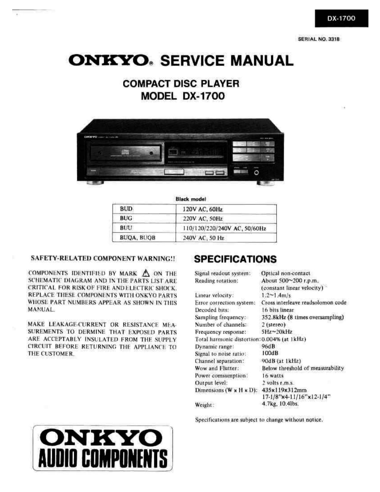
Onkyo DX 1700 Service Manual
This is the 26 pages manual for Onkyo DX 1700 Service Manual.
Read or download the pdf for free. If you want to contribute, please upload pdfs to audioservicemanuals.wetransfer.com.
Extracted text from Onkyo DX 1700 Service Manual (Ocr-read)
Page 2
D -1700
TABLE OF CONTENTS
Specifications ............................. 1
Service procedures ........................... 2
Portection on eyes from laser beam during servicing ..... 2
Laser warning labels .......................... 2
Caution on replacement of pickup ................ 4
Exploded view»parts list ....................... 4
Exploded view ............................. 5
Mechanism-exploded View ...................... 6
Parts list ................................. 7
Disassembling procedures ...................... 8
Adjustment procedures ....................... 12
Trouble shooting guide ....................... 15
IC block diagram and description ................ l7
Microcomputer descriptions ................... 23
Schematic diagram .......................... 25
Waveform of each section ..................... 29
Pc board View & Parts list ..................... 3]
Block diagram ............................. 35
Packing View .............................. 36
SERVICE PROCEDURES
1. Safety-check out
After correcting the original service problem, perform the
following safety check before releasing the set to the
customer:
Connect the insulating-resistance tester between the plug
of power supply cable and chassis.
Specifications: more than lOMohrn at 500V.
2. Voltage selector (rear panel)
Worldwide models are equipped with a voltage selector to
conform with local power supplies Be sure to set this selector
to match the voltage of the power supply in your area before
turning the power switch on. Voltage is changed by turning
the voltage selector with a screwdriver or similar instrument
to the 110V. 120V, 220V or 240V position. Confirm that the
selector has been set to the correct position before turning
the power switch on. If there is no voltage selector switch on
the unit you have purchased. it can only be used in areas
where the power supply voltage is the same as that ofthe unit.
at AC 1 10V at AC 120V at AC 220V at AC 240V
Fig. 1
PROTECTION OF EYES FROM LASER BEAM DURING SERVICING
This set employs a laser. Therefore, be sure to follow
carefully the instructions below when servicingi
WARNINGl!
WHEN SERVICING. DO NOT APPROACH THE LASER
EXIT WITH THE EYE TOO CLOSELY. IN CASE IT IS
NECESSARY TO CONFIRM LASER BEAM EMMISION.
BE SURE TO OBSERVE FROM A DISTANCE OF MORE
THAN 30cm FROM THE SURFACE OF THE OBJECTIVE
LENS ON THE OPTICAL PICK-UP BLOCK.
LASER WARNING LABEL
The label shown below are affixed
1, Certification label (120V model)
This label is located on the back panel.
PRODUCT IS CERTIFIED BY THE MANUFACTURER T0 OJMPLY
WTIH DHHS RULES 21 CFR SUBCHAPTER J APPLICABLE AT THE
DATE OF MANUFACTURE.
MANUFACTURED
Fig. 2
Laser Diode Properties
0 Material: GaAS/GaAlAs
o Wavelength: 780nm
0 Emission Duration: continuous
0 Laser output: max. 0.5mW'
*This output is the value measured at a distance
about 1.8mm from the objective lens surface
on the Optical Pick-up Block.
2. Class I label (Except 120V model)
This label is located on the back panel.
"CLASS I LASER
PRODUCT"
Fig. 3