Onkyo DX 100 Service Manual

This is the 36 pages manual for Onkyo DX 100 Service Manual.
Read or download the pdf for free. If you want to contribute, please upload pdfs to audioservicemanuals.wetransfer.com.

Page: 1 / 36
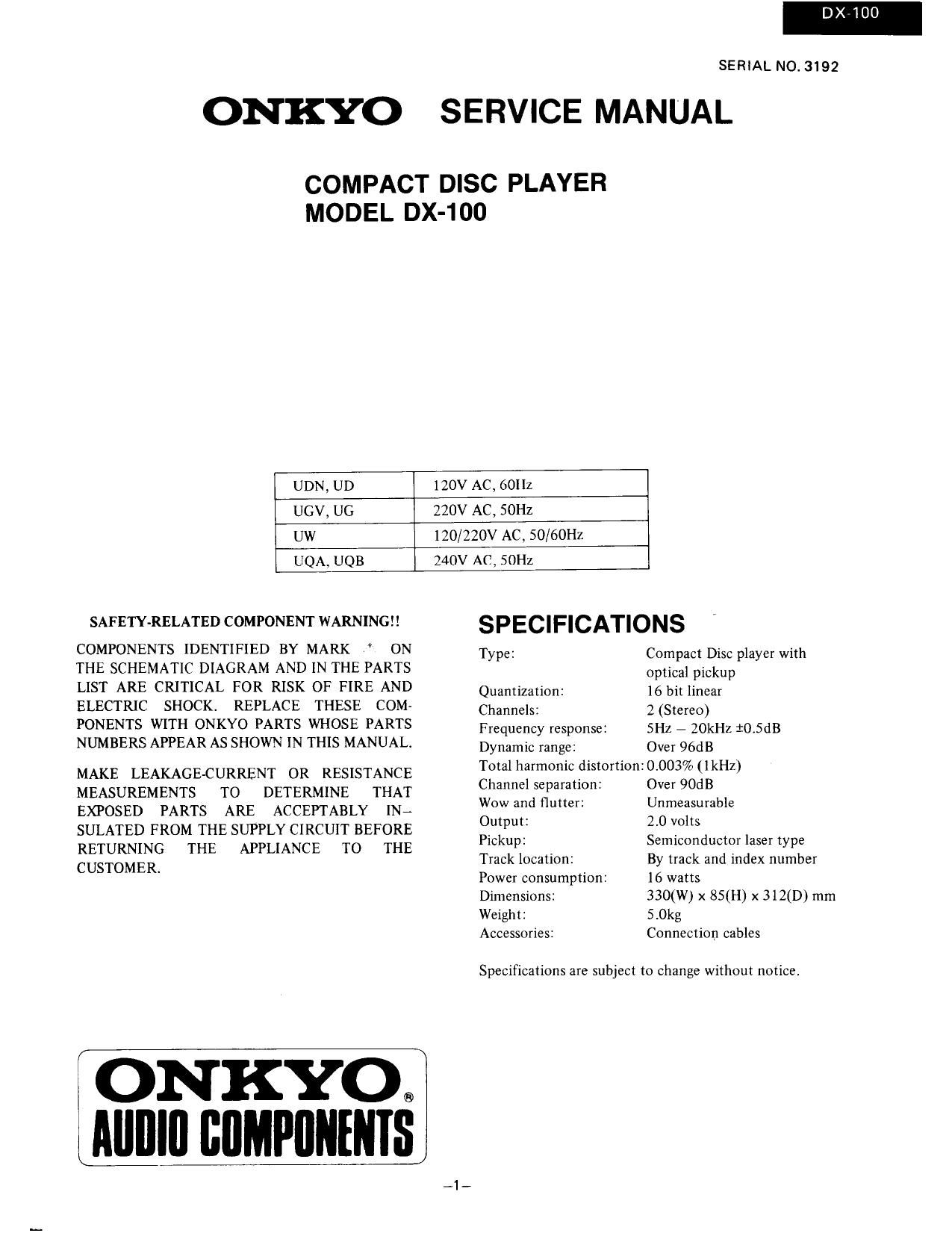
Onkyo DX 100 Service Manual

Extracted text from Onkyo DX 100 Service Manual (Ocr-read)


Page 1

ONKYO

DXVIOO

SERIAL NO. 3192

SERVICE MANUAL

COMPACT DISC PLAYER
MODEL DX-1OO

UDN, UD

120V AC, 60Hz

ucv, UG

220V AC, SOHz

UW

120/220V AC. 50/60HZ

UQA, UQB

240V AC, SOHZ

SAFETY-RELATED COMPONENT WARNING

COMPONENTS IDENTIFIED BY MARK ON
THE SCHEMATIC DIAGRAM AND IN THE PARTS
LIST ARE CRITICAL FOR RISK OF FIRE AND
ELECTRIC SHOCK. REPLACE THESE COM-
PONENTS WITH ONKYO PARTS WHOSE PARTS
NUMBERS APPEAR AS SHOWN IN THIS MANUAL.

MAKE LEAKAGE-CURRENT OR RESISTANCE
MEASUREMENTS TO DETERMINE THAT
EXPOSED PARTS ARE ACCEPTABLY IN;
SULATED FROM THE SUPPLY CIRCUIT BEFORE
RETURNING THE APPLIANCE TO THE
CUSTOMER.

ONKYQ
iAllllllI IIIIMPIIIIIIIIS

SPECIFICATIONS

Type: Compact Disc player with
optical pickup

Quantization: 16 bit linear

Channels: 2 (Stereo)

Frequency response: 5H2 - ZOkHz 10.5dB

Dynamic range; Over 96dB

Total harmonic distortion: 0.003% (lkHz)

Channel separation: Over 90:13

Wow and flutter: Unmeasurable

Output: 2.0 volts

Pickup: Semiconductor laser type

Track location: By track and index number

Power consumption: 16 watts

Dimensions: 330(W) x 850'!) x 312(D) mm

Weight: 5,0kg

Accessories: Connection cables

Specifications are subject to change without notice.

Page 2

DX-iOO

LASER PICK-UP REMOVAL

1, Remove the disc tray and pick-up cover. (See Figure 21) 5. Remove outside spring (E) r

2. Remove four screws (A) of mecha. chassis (B) . 6. Remove two screws (F) , and the laser pick-up (G) will
3. Remove two screws (C) of guide rack assembly (D) , be removed.

4 Sliort»circuit the RC. Board using short plug, then

remove connector and leads (Refer to CAUTIONS 0N
REPLACEMENT OF PICK-UR)

Eur/#26 CF 7;? SPQNAA) (1)2 x 6mm, Screw

(Mbefl mam C 1mm ;
Tea Jump yaw firsr

(B) Mecha Chassis

(C) $2 x 6mm, Screw

Guide Rack Assembiy

Figure 22

Figure 21

(E) Spring
(F) (b3 x 4mm, Screw

(G) Laser Pickup Figure 24

Figure 23

710,