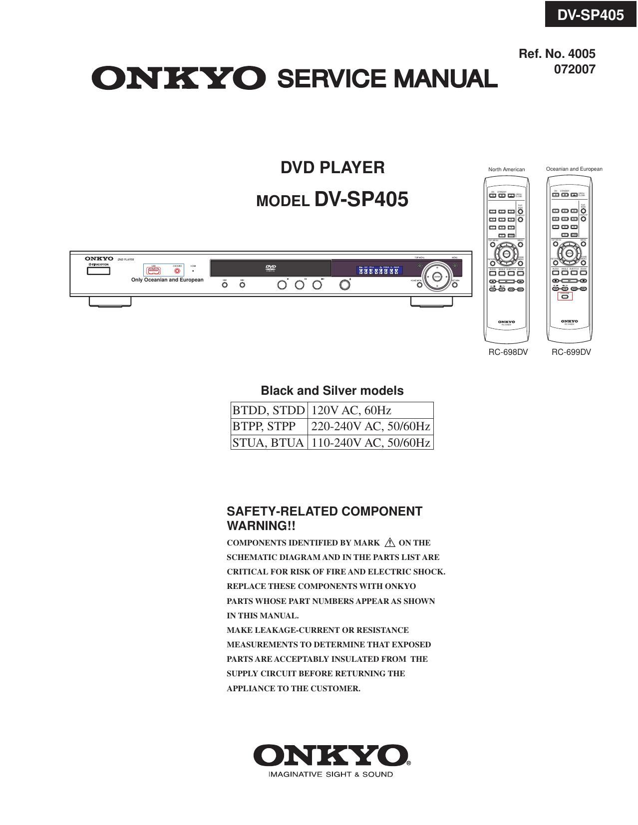
Onkyo DVSP 405 Service Manual
This is the 92 pages manual for Onkyo DVSP 405 Service Manual.
Read or download the pdf for free. If you want to contribute, please upload pdfs to audioservicemanuals.wetransfer.com.
Extracted text from Onkyo DVSP 405 Service Manual (Ocr-read)
Page 1
D P405
Ref. No. 4005
ONKYO SERVICE MANUAL °72°°7
DVD PLAYER
MODEL DV-SP405
ONKYO mm
mum... ,_ w.
l:| [El] (:3 -
only Oceanlan and European
Black and Silver models
BTDD, STDD 120V AC, 60Hz
BTPP, STPP 220-240V AC, 50/60Hz
STUA, BTUA 110-240V AC, 50/60Hz
SAFETY-RELATED COMPONENT
WARNING! !
COMPONENTS IDENTIFIED BY MARK A ON THE
SCHEMATIC DIAGRAM AND IN THE PARTS LIST ARE
CRITICAL FOR RISK OF FIRE AND ELECTRIC SHOCK.
REPLACE THESE COMPONENTS WITH ONKYO
PARTS WHOSE PART NUMBERS APPEAR AS SHOWN
IN THIS MANUAL.
MAKE LEAKAGE-CURRENT OR RESISTANCE
MEASUREMENTS TO DETERMINE THAT EXPOSED
PARTS ARE ACCEPTABLY INSULATED FROM THE
SUPPLY CIRCUIT BEFORE RETURNING THE
APPLIANCE TO THE CUSTOMER.
ONKYO.
IMAGINATIVE SIGHT SI SOUND
Nunh American Oceaman and European
RC-698DV RC-699DV
Page 71
DV-SP4 5
IC BLOCK DIAGRAM/TERMINAL DESCRIPTIONS-3
0 Pin Function
Abbreviations:
- SR: Slew Rate
- PU: Pull Up
- PD: Pull Down
- SMT: Schmitt Trigger
- 4mA~16mA: Output buffer driving strength.
Pln I Main I Alt. I Type I Description
RF Interface (26)
191 RFGND18 Ground Analog ground
192 RFVDD18 Power Analog power 1.8V
212 OSP Analog output RF Offset cancellation capacitor connecting
213 OSN Analog output RF Offset cancellation capacitor connecting
214 RFGC Analog output RF AGC loop capacitor connecting for DVD-ROM
Current reference input. It generates reference current for
215 IREF Analog Input RF path. Connect an external 15K resistor to this pin and
AVSS
216 AVDD3 Power Analog power 3.3V
1 AGND Ground Analog ground
2 DVDA Analog Input AC ooupled input path A
3 DVDB Analog Input AC coupled input path 3
4 DVDC Analog Input AC coupled input path C
5 DVDD Analog Input AC ooupled input path D
6 DVDRFIP Analog Input AC coupled DVD RF signal input RFIP
7 DVDRFIN Analog Input AC coupled DVD RF signal input RFIN
8 MA Analog Input DC coupled main~beam RF signal input A
9 ME Analog Input DC coupled main-beam RF signal input B
10 MC Analog Input DC coupled main-beam RF signal input C
11 MD Analog Input DC coupled main-beam RF signal input D
12 SA Analog Input DC coupled sub-beam RF signal input A
13 SB Analog Input DC coupled sub
14 SC Analog Input DC coupled sub-beam RF signal input C
15 SD Analog Input DC coupled sub-beam RF signal input D
16 CDFON Analog Input CD focusing error negative input
17 CDFOP Analog Input CD focusing error positive input
18 TNI Analog Input 3 beam satellite PD signal negative input
ALPC (4)
19 TPI Analog Input 3 beam satellite PD signal positive input
20 M011 Analog Input I Laser power monitor input