Onkyo DVS 939 Service Manual

This is the 35 pages manual for Onkyo DVS 939 Service Manual.
Read or download the pdf for free. If you want to contribute, please upload pdfs to audioservicemanuals.wetransfer.com.

Page: 1 / 35
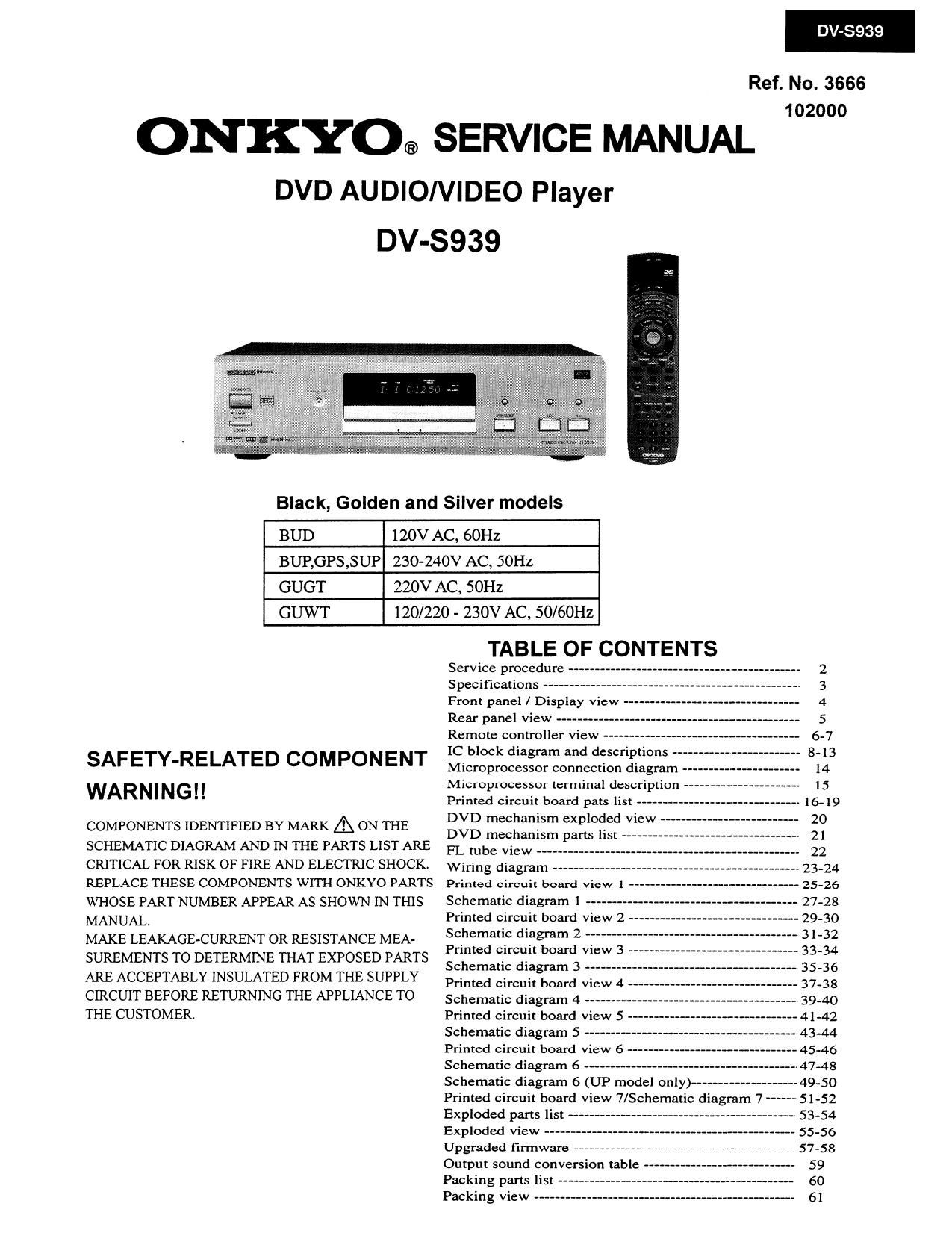
Onkyo DVS 939 Service Manual

Extracted text from Onkyo DVS 939 Service Manual (Ocr-read)


Page 1

DV-S939

Ref. No. 3666
102000

ONKYO® SERVICE MANUAL

DVD AUDIONIDEO Player
DV-S939

Black, Golden and Silver models

BUD 120V AC, 60Hz
BUP,GPS,SUP 230-240V AC, 50Hz

GUGT 220V AC, 50Hz

GUWT 120/220 - 230V AC, 50/60Hz

SAFETY-RELATED COMPONENT
WARNING! !

COMPONENTS IDENTIFIED BY MARK A ON THE
SCHEMATIC DIAGRAM AND IN THE PARTS LIST AR.E
CRITICAL FOR RISK OF FIRE AND ELECTRIC SHOCK.
REPLACE THESE COMPONENTS WITH ONKYO PARTS
WHOSE PART NUMBER APPEAR AS SHOWN IN THIS
MANUAL.

MAKE LEAKAGE-CURRENT OR RESISTANCE MEA-
SUREMENTS TO DETERMINE THAT EXPOSED PARTS
ARE ACCEPTABLY INSULATED FROM THE SUPPLY
CIRCUIT BEFORE RETURNING THE APPLIANCE TO
THE CUSTOMER

TABLE OF CONTENTS
Service procedure -- 2
Specifications ------- 3
Front panel / Display view -- 4
5

Rear panel View ------------
Remote controller view -
IC block diagram and descriptions --


Microprocessor connection diagram --- 14
Microprocessor terminal description 15
Printed circuit board pats list ---» 16-19
DVD mechanism exploded view -- 20
DVD mechanism parts list -- 21
FL tube view ---- 22
Wiring diagram 23-24
Printed circuit board View 1 - 25-26
Schematic diagram 1 ------ 27-28
Primed circuit board view 2 - 29-30

Schematic diagram 2 ---------
Printed circuit board View 3 ---
Schematic diagram 3 -------
Printed circuit board View 4 »
Schematic diagram 4 -
Printed circuit board View 5 -
Schematic diagram 5 -
Printed circuit board View 6 -
Schematic diagram 6 ---------------------
Schematic diagram 6 (UP model only)-
Printed circuit board view 7/Schematic diagram 7 --
Exploded parts list ----------------------
Exploded view -------
Upgraded firmware -
Output sound conversion table
Packing parts list
Packing View ------

Page 2

D 6939

SERVICE PROCEDURE

1. Replacing the fuses

E- This symbol located near the fuse indicates that the

fuse used is show operating type, For continued protection against
fire hazard, replace with same type fuse , For fuse rating, refer to
the marking adjcst to the symbol.

a Ce symbole indique que le fusible utilise est e lent.

Pour urie protection pennanente, n'utiliser que des fusibles de meme
type. Ce demier est indique la qu le present symbol est apposre.

REF.NO. PART NO. DESCRIPTION
F9001 252158 l.6A-UUI'-237, Fuse
252073 1.6A-SE-EAW, FUSE

NOTE : : 120 V 60Hz model only
: 230 V SOHZ model only
: 120/220-230 V 50/60Hz model only
: 220 V 50Hz model only

2. Safety-check out

(Only U.S.A. model)

After correcting the original service problem perform the
follwing safety check before releasing the set to the customer
Connect the insulating-resistance tester between the plug of
power supply cord and terminal GND on the back panel.
Specifications: More than 10Mohm at 500V

3. Regional restriction codes (Region Number)
Regional restriction codes are built into DVD players and DVD
videos for each sales region. It" the regional code of the DVD
receiver dose not match one of the regional codes on the DVD
video, playback is not possible.

The regional number can be found on the rear panel of the DVD
receiver. (e.g. for Region 1)

4. CAUTION labels

WARNING

RISK OF EL CTRIV SH CK
D0 "GET OPEN 0

RISDUE DE CHOC ELECTRIDUE NE
PAS OUVRIR

WARNING : TO REDUCE THE RISK. OF
ELECTRIC SHOCK, DO NOT REMOVE
CUVER(0R BACK). N0 USERSERVICEABLE


PART INSIDE, REFER SERVICING T0
QUALIFIED SERVICE PERSONNEL.

5. Replacement of DVD mechanism

The laser diode in the optical pickup block is so
sensitive to static electricity, surge current and etc,
That the components are liable to be broken down

or its reliablity remarkable deteriorated.

During repair, carefully take the following precautions.
Do not touch the optical pickup object lens

with the hands.

1. Remove the top cover with eight screws.

2. Remove the PC board(NAAR-6953 Main circuit
PCB} with two screws.

3. Remove the mechanism cover with four screws.

4. Solder the LD output lands on the DVD optical pickup.

5. Replace the pickup mechanism assembly.

Unsoder the laser diode output lands.

Laser diode

output lands

The lightning Ilash with arrowhead symbol, within an equilateral triangle, is
intended to alert the user to the presence ol uninsulated dangerous voltage
wilhin the product's enclosure that may be of sufficient magnitude to constitute
a risk 01 electric shock to persons.

The exclamation point within an equilateral triangle is intended to alert the user
to the presence of important operating and maintenance (servicing) instruction
in the literature accompanying the appliance.

WARNING: TO REDUCETHE RISK OF FIRE OR ELECTRIC SHOCK, DO NOT EXPOSETHIS APPLIANCETO RAIN
OR MOISTURE. DANGEROUS HIGH VOLTAGES ARE PRESENT INSIDETHE ENCLOSURE. DO NOT OPEN THE
CABINET. REFER SERVICING T0 QUALIFIED PERSONNEL ONLY.

CAUTION : TO PREVENT ELECTRIC SHOCK. MATCH WIDE BLADE 0F PLUG T0 WIDE SLOT. FULLY INSERT.

ATTENTION : POUR EVITER LES CHOCS ELECTRIQUE, iNTRODUIRE LA LAME LA PLUS LARGE DA LA FICHE DANS LA
BOHNE CORRESPONDANTE DA LA PRlSE ET POUSSER JUSGU' AU FOND.

Page 32

DV-SQ39

3. Factory setting confirmation

3-1. Turn power switch to ON to set the standby mode at no disc condition.
3-2. Press and hold down DISPLAY and STANDBY button.

3-3. Tum POWER to OFF, and pull out the power cord.

3-4. Confirm that display on me monitor TV is as follow.

D WT/GT P PS
Picture TV/SHARP 4 :3 LB
BLACKER THAN BLACK OFF
Progressive 4 : 3 out FULL
Progressive Conversion AUTO
AUDIO AUDIO OUT SELECT Bitsream
Language On-screen/Disc Eng
AUDIO Eng
Subtitle -
Display On-Screen display ON
BACK GRAND GRAY
Screen Saver ON
Operation PAUSE/STILL AUTO
PARENTAL LOCK Off
Remote Confirmation On
TITLE/GROUP STOP Off
PBC 0n
PRIORITY CONTENTS DVD-AUDIO
NOTE:

I. The firmware and setup data are not available
as service parts.

2. For more information, consult ONKYO authorized
service station in your aria.

LSSW