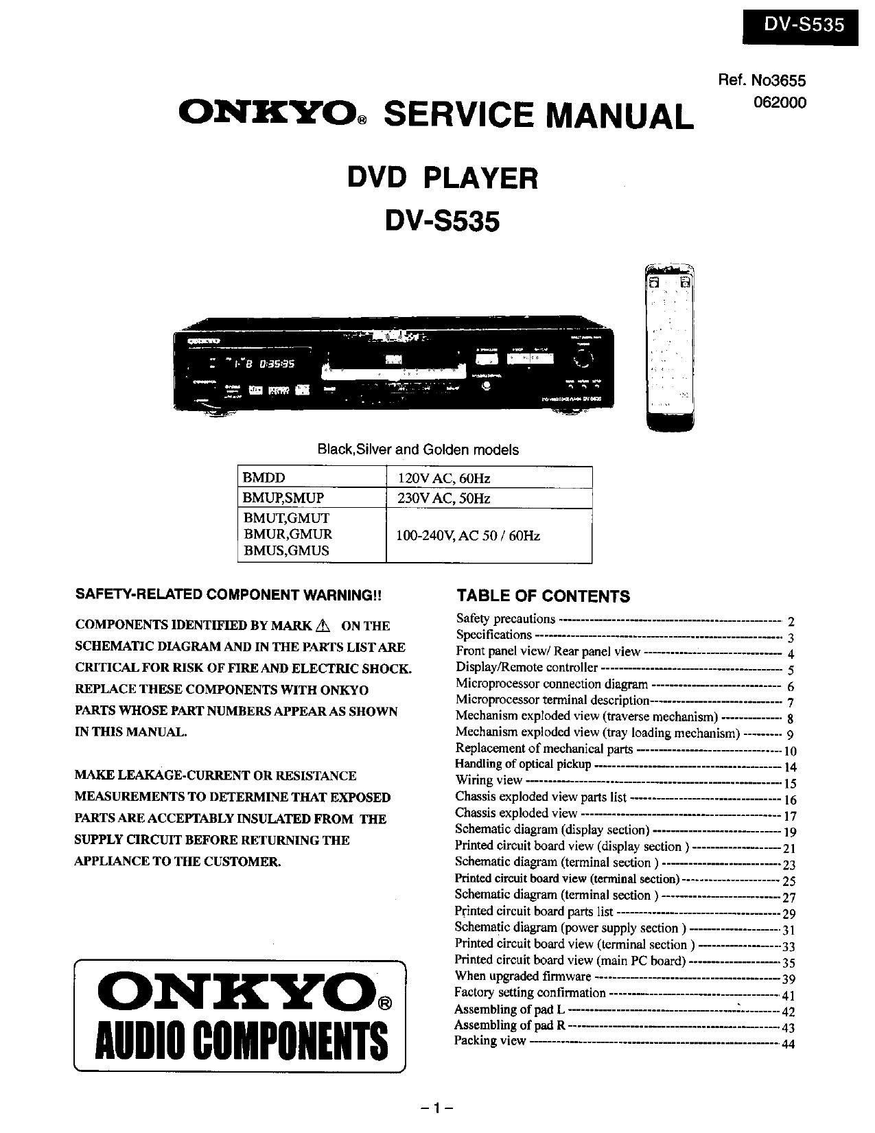
Onkyo DVS 535 Service Manual
This is the 23 pages manual for Onkyo DVS 535 Service Manual.
Read or download the pdf for free. If you want to contribute, please upload pdfs to audioservicemanuals.wetransfer.com.
Extracted text from Onkyo DVS 535 Service Manual (Ocr-read)
Page 1
DV-3535
Ref. N03655
062000
ONKYO® SERVICE MANUAL
DVD PLAYER
DV-S535
BIack,Si|ver and Golden models
BMDD 120V AC, 60Hz
BMUP,SMUP 230V AC, 50Hz
BMUT,GMUT
BMUR,GMUR 100-240V, AC 50/ 601-12
BMUS,GMUS
SAFETY-RELATED COMPONENT WARNING
COMPONENTS IDENTIFIED BY MARK A ON THE
SCHEMATIC DIAGRAM AND IN THE PARTS LISTARE
CRITICAL FOR RISK OF FIRE AND ELECTRIC SHOCK.
REPLACE THESE COMPONENTS WITH ONKYO
PARTS WHOSE PART NUMBERS APPEAR AS SHOWN
IN THIS MANUAL.
MAKE LEAKAGE-CURRENT 0R RESISTANCE
MEASUREMENTS TO DETERMINE THAT EXPOSED
PARTS ARE ACCEPTABLY INSULATED FROM THE
SUPPLY CIRCUIT BEFORE RETURNING THE
APPLIANCE TO THE CUSTOMER.
ON KYOé
Alllllll flflMPIIllEllTS
TABLE OF CONTENTS
Safety precautions ~-
Speoifications --------
Front panel view/ Rear panel view ---
Display/Remote controller ---------
Microprocessor connection diagram -
Microprocessor terminal description ------------------
Mechanism exploded view (traverse mechanism) --
Mechanism exploded view (tray loading mechanism)
Replacement of mechanical parts -
Handling of optical pickup -..
Wiring View ---------------
Chassis exploded view parts list
Chassis exploded view -----------
Schematic diagram (display section) -
Printed circuit board view (display section )
Schematic diagram (terminal section ) ----
Printed circuit board View (wmu'nal section)
Schematic diagram (terminal section ) ----
Printed circuit board parts list --------------
Schematic diagram (power supply section ) -
Printed circuit board view (terminal section ) -
Printed circuit board view (main PC board) -
When upgraded firmware -----
Factory setting continuation --
Assembling of pad L ---
Assembling of pad R
Packing view -----------
Page 2
DV-5535
OPERATING INSTRUCTIONS
SAFETY PRECAUTIONS
The lightning flash with arrowhead symbol, within an equilateral triangle, is
intended to alert the user to the presence of uninsulated 'dangerous voltage"
within the products enclosure that may be of suiticient magnitude to constitute
a risk of electric shock to persons.
a WARNWG g
RISK %Wsm
ISOUE DE choc ELECTRIOUE NE
PAS OWRIR
WARNING 2 TO REDUCE THE RISK. OF
ELECTRIC SHOCK. DO NOT REMOVE
COVER (0R BACK). N0 USERSERVICEABLE
PART INSIDE. REFER SERVICING T0
DUAL | F I ED SERV | CE PERSONNEL.
The exclamation point within an equilateral triangle is Intended to alert the user
to the presence of important operating and maintenance (servicing) instruction
in the literature accompanying the appliance.
WARNING : TO REDUCE THE RISK OF FIRE OR ELECTRIC SHOCK, DO NOT EXPOSE THIS APPLIANCE TO RAIN
OR MOISTURE. DANGEROUS HIGH VOLTAGES ARE PRESENT INSIDE THE ENCLOSURE. DO NOT OPEN THE
CABINET. REFER SERVICING TO QUALIFIED PERSONNEL ONLY.
CAUTION : TO PREVENT ELECTRIC SHOCK, MATCH WIDE BLADE OF PLUG TO WIDE SLOT. FULLY INSERT.
ATTENTION : POUR EVITER LES CHOCS ELECTRIOUE, INTRODUIRE LA LAME LA PLUS LARGE DA LA FICHE DANS LA
BORNE CORRESPONDANTE DA LA PRISE ET POUSSER JUSOU AU FOND.
PRECAUTIONS
Replacing the fuses
For continued protection against risk fire, replace only
with same type and same rating fuse.
CIRCUIT No. PART No. DESCRIPTION
F901 252071 1.25A-SE-EAWK Fuse
252146 or 1.25A-TSC or
252157 1.25A-UIJF-237, Fuse
E This symbol located near the fuse indicates that the fuse
used is fast operating type. For continued protection against fire
hazard, replace with same type fuse For fuse rating refer to the
marking adjacent to the symbol.
-.:}- Ce symbole indique que le fusible utlise est a rapide.
Pour une protection permanente, n'utiliser que des fusibles de meme
type, Ce darrnier est indique la qu le present symbol est appose,
LASER BEAM CAUTION LABEL
caunou - VISIBLE LASER RADIATION WHEN OPEN
AND INTERLOCK DEFEATED.
DO NOT STARE INTO BEAM.
ant/Ans. - LASEHSTRALING VED ABNING. Nita
SIKKERHEDSAFBRVDEHE ER UDE AF
FUNKTION. SE IKKE IND I STRRLEN.
Arm/mean LASERTRALING N a DEKsEL APNEs
OG SIKKERHEDS S BHYTES.
STIRR IKKE INN I STRALEN.
vuwue - OsvtiLKgLASERSTRALNIKIG NARADENNA
DEL R PPNAD OCH SP RRAH
WAVE LENGTH :650nm UHKOPPLADE SYIRRA EJ IN t STR LEN.
W vmr - AVAI'I'AESSA JA SUOJALUKITUS
' OHITEI'TAESSA OLET ALI'TIINA LASER-
! , 550M SATEILYLLE ALA 'ruuo-ra SATEESEEN.
ax; b-f-HUJ : o. W 2 I -lt.\f=UIIllEttfl-1=Utbzlmu-~Hw
mutt. e-A amt: want-w amaze.
SN 29692564
When the power supply is being turned on, you may not remove this laser cautions
label, radiation of a laser may he received.
Pickup Head consists of a laser diode that is very susceptible to external static electricity.
Although it operates properly after replacement, if it w subject to electrostatic discharge
during replacement, its life might be shortened. When replacing, use a conductive mat,
soldering iron with ground wire, etc. to protect the laser diode from damage by static
electricity. And also, the LSI and IC are same as above.
-2-
Page 13
DV-SS35
HANDLING OF OPTICAL PICKUP
The laser diode in the optical pickup block is so sensitive to static electricity , surge current and etc.
that the components are liable to be broken down or its reliability remarkably deteriorated.
During repair , carefully take the following precautions.
1. Work according the undermentioned procedure when remove the DVD mechanism from the main body of the set.
1-1. LD short terminal on the pickup PC board is shorted with solder. (Fig-1)
1-2. Flexible flat cable connected with the DVD mechanism is removed.
1-3. The DVD mechanism is removed from the main body of the set.
2. DVD mechanism according to a reverse procedure at the installation.
3. Short circuited first of LD short land when the main PC board(SD-3OB 188) is removed from the main body
of the set with solder.
Optical pickup
HANDLING OF MAIN PC BOARD
1. Work according the undermentioned procedure when remove the main PC board from the main body of the set.
1-1. LD short land on the pickup PC board is shorted with solder. (Fig-1)
1-2. Flexible flat cable and the socket connected are removed.
1-3. Four machine screws are removed.
2. Main PC board according to a reverse procedure at the installation.
1-2(Flexible flat cable)
1-3(screws) I I I I 1-3(screws)
w [M
1-2.(Flexible flat cable) a
1-2.(Socket)
Iain PC board
m 'fi' Hm
1-3(screws) I I I I 1-3(screws),
l-2.(Flexible flat cable)
Fig.2
_ 14 _